


Service Manual 13
Installation
13
8
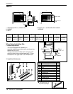
Foam-Strip
Screw(Type A)
Screw(Type A)
Power cord
TIMER
E
N
E
R
G
Y
S
A
V
E
R
MODE
O
n
/O
f
f
O
n
/O
ff
Fa
n
C
o
o
l
H
e
a
t
T
I
M
E
R
E
N
E
R
G
Y
S
A
V
E
R
M
O
D
E
On/OffOn/Off
FanCool
Heat
TIMER
ENERGY
SAVER
MODE
On/OffOn/Off FanCool
Heat
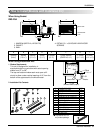
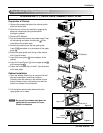
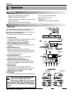
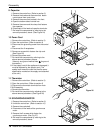
10. Slide the unit into the cabinet.(See Fig. 8)
CAUTION:
For security purpose, reinstall
screws (Type A) at the cabinet's sides.
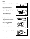
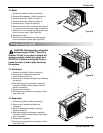
11. Cut the Foam-Strip to the proper length and insert
between the upper and lower window sash.
(See Fig. 9)
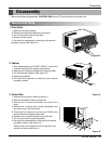
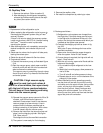
12. Attach the window Locking Bracket with a type C
screw. (See Fig. 10)
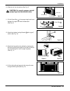
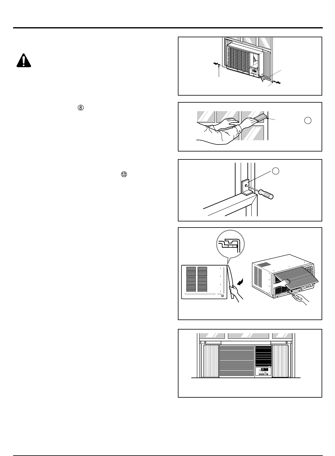
13. Attach the front grille to the cabinet by inserting the
tabs on the grille into the tabs on the front of the cab-
inet. Push the grille in until it snaps into place.
(See Fig. 11)
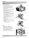
14. Lift the inlet grille and secure it with a type A screw
through the front grille.(See Fig. 12)
Figure 11
Figure 8
Figure 9
Figure 10
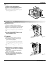
Figure 13
Figure 12