


Heat Controller, Inc. HTV/HTD/HTH SERIES Engineering Design Guide
8
Heat Controller GeoMax 2
n
Geothermal Heat Pump Systems
ClimateMaster Geothermal Heat Pump Systems
TT
25
All Products Technical Guide: 2008 - 2009
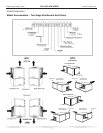
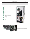
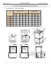
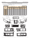
Dimensions — Vertical Upflow Tranquility
27™
Access Panels
Top View-Left Return
Top View-Right Return
U
R
S
Isometric
View
Left Return Left View
- Filter Rack Knife Edge
T
C
Power Supply
3 / 4" [19.1mm]
HV Knockout
1 / 2" [12.7mm]
Knockout
Low Voltage
1 / 2" [12.7mm]
LV Knockout
Condensate
3 / 4" Glue
(PVC Socket)
Front-View
K
1.00 [25.4 mm]
G
JH
E
F
D
L
Air Coil
Field Installed
Discharge Flange
Front
Back
U
R
S
T
C
Back
Front
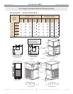
Right Return Right View
- Filter Rack Knife Edge
BSP
CAP
Deluxe Filter Bracket
ASP
ASP
Air Coil
Front
P
N
O
Q
Front
2' (61cm)
Optional
Service
Access
Left Rtn
(right
Opposite)
N
B
P
A
O
M
2' (61cm)
Service
1.68 [42.7 mm]
Residential
Filter Rack
Shown
Residential
Filter Rack
Shown
1.18 [30.0 mm]
1.63
[41.4 mm]
1
2
5
3
4
Legend
CAP=Control Access Panel
CSP=Compressor Service Panel
BSP=Blower Service Panel
ASP=Alternate Service Panel
CSP
CAP
CSPASP
CSP
Air Coil
Air Coil Side
Air Coil Side
Rev.: 03/15/04B
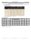
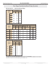
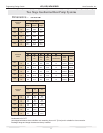
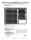
Vertical
Upflow
Model
Discharge Connection
Duct Flange Installed (+/- 0.10 in, +/- 2.5mm)
Return Connection
Standard Deluxe Filter Rack
(+/- 0.10 in, +/- 2.5mm)
M
Left
Return
N
O
Supply
Width
P
Supply
Depth
Q
Right
Retuen
R
S
Return
Depth
T
Return
Height
U
026
in
cm
7.8
18.3
5.8
14.8
14.0
35.6
14.0
35.6
4.9
12.4
1.7
4.2
22.2
56.4
26.2
66.4
1.5
3.9
038
in
cm
6.4
16.1
6.3
16.0
18.0
45.7
18.0
45.7
5.3
13.5
2.1
5.4
27.1
68.9
26.1
66.4
1.5
3.9
049
in
cm
6.4
16.1
6.3
16.0
18.0
45.7
18.0
45.7
5.3
13.5
2.1
5.4
27.1
68.9
30.1
76.5
1.5
3.9
064
in
cm
6.4
16.1
6.3
16.0
18.0
45.7
18.0
45.7
5.3
13.5
2.1
5.4
27.1
68.9
34.1
86.7
1.5
3.9
072
in
cm
6.4
16.1
6.3
16.0
18.0
45.7
18.0
45.7
5.3
13.5
2.1
5.4
27.1
68.9
34.1
86.7
1.5
3.9
070
060
048
036
024
Dimensions – Vertical Upow
7
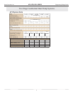
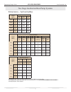
Two Stage Geothermal Heat Pump Systems