


7
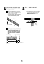
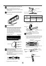
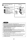
Main PCB
Low panel
Lower panel
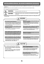
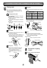
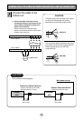
CAUTION
When install, make sure
that the remaining parts
must be removed clearly
so as not to damage the
piping and drain hose,
especially power cord
and connecting cable.
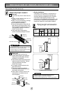
Route the indoor tubing and the drain hose in
the direction of rear left.
Insert the connecting cable into the indoor unit
from the outdoor unit through the piping hole.
■ Do not connect the cable to the indoor unit.
■ Make a small loop with the cable for easy
connection later.
Drain hose
For left rear piping
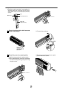
A
B
Remove the front right side panel by the arrow.
■ The connector can be disconnected by pulling it
while pressing the connector's hook.
■ Remove the 1 screw
for fixing low panel.
B
Remove the lower panel by the arrow.
■ Take care not to scratch the wall and mat to
drop.
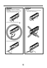
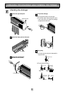
C
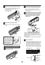
Indoor unit installation
■ Hook the indoor unit onto the upper portion of the
installation plate.(Engage the three hooks of the
rear top and rear lower of the indoor unit with the
upper edge and lower edge of the installation
plate.) Ensure that the hooks are properly seated
on the installation plate by moving it left and right.
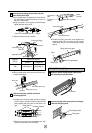
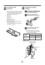
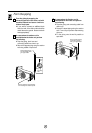
D
NOTE: If the drain hose is routed inside the room,
insulate the hose with an insulation material*so that
dripping from "sweating"(condensation) will not damage
furniture or floors.
*Foamed polyethylene or equivalent is recommended.
Installation
plate
Three upper
hooks
Installation plate
Indoor unit
Three lower
hooks
Setting line
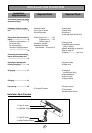
Tape the tubing, drain hose and the connecting
cable. Be sure that the drain hose is located at
the lowest side of the bundle. Locating at the
upper side can cause drain pan to overflow
inside the unit.
C
Connecting
cable
Loop
Gas side
piping
Liquid side
piping
Drain hose