


XV. STARTUP
1. Turn thermostat to “OFF,” turn “on” power supply at discon-
nect switch.
2. Turn temperature setting as high as it will go.
3. Turn fan switch to “ON.”
4. Indoor blower should run. Be sure it is running in the right
direction.
5. Turn fan switch to “AUTO.” Turn system switch to “COOL”
and turn temperature setting below room temperature. Unit
should run in cooling mode.
6. Is outdoor fan operating correctly in the right direction?
7. Is compressor running correctly.
Record the following after the unit has run some time.
A. Operating Mode _______________________________
B. Discharge Pressures (High) _____________PSIG [kPa]
C. Vapor Pressure at Compressors (Low) _____PSIG [kPa]
D. Vapor Line Temperature at Compressors ______°F [C°].
E. Indoor Dry Bulb __________________________°F [C°].
F. Indoor Wet Bulb__________________________°F [C°].
G. Outdoor Dry Bulb_________________________°F [C°].
H. Outdoor Wet Bulb ________________________°F [C°].
I. Voltage at Contactor ________________________Volts
J. Current at Contactors ______________________ Amps
K. Model Number_________________________________
L. Serial Number _________________________________
M.Location______________________________________
N. Owner _______________________________________
O. Date_________________________________________
8. Turn thermostat system switch to “HEAT.” Unit compres-
sors should stop. Raise temperature setting to above room
temperature. Unit should run in heating mode and auxiliary
heaters, if installed, should come on.
9. Check the refrigerant charge using the instructions located
on unit charging chart. Replace service port caps. Service
port cores are for system access only and will leak if not
tightly capped.
10. Adjust discharge air grilles and balance system.
11. Check ducts for condensation and air leaks.
12. Check unit for tubing and sheet metal rattles.
13. Instruct the owner on operation and maintenance.
14. Leave “INSTALLATION” and ”USE AND CARE“ instruc-
tions with owner
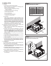
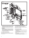
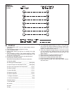
A0823-01
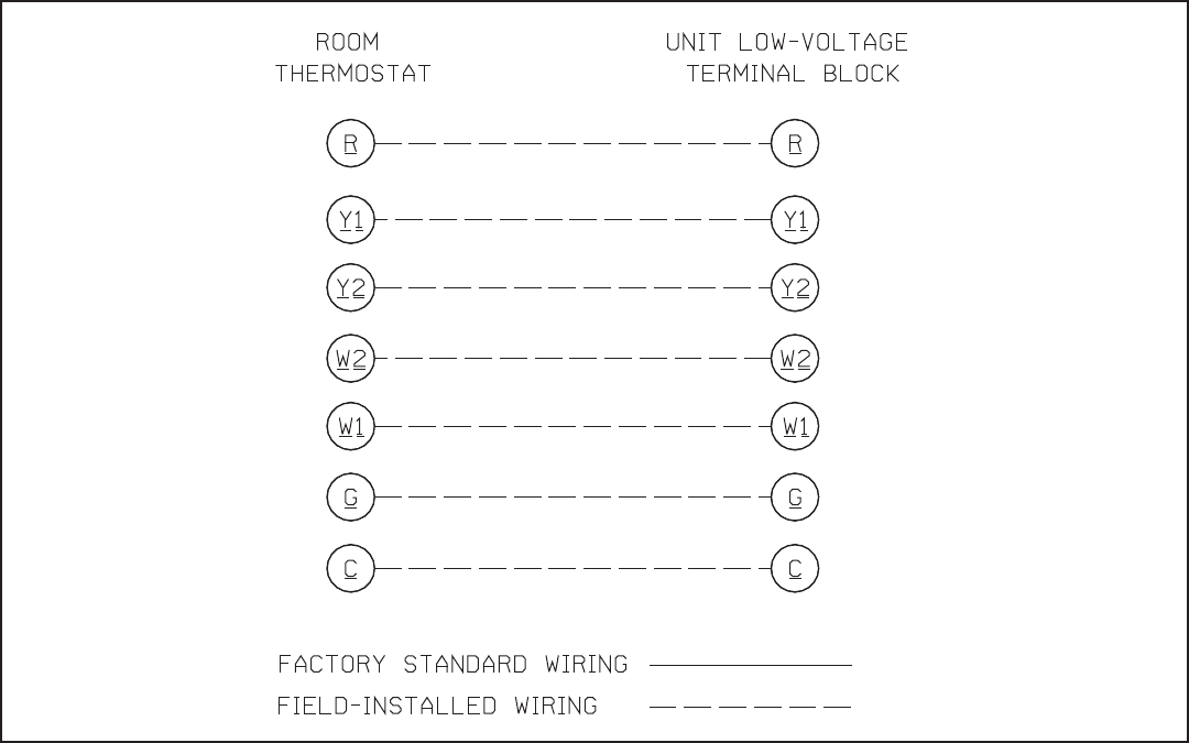
FIGURE 15
THERMOSTAT
CONNECTIONS
DIAGRAM
17