


VII. DUCTWORK
Ductwork should be fabricated by the installing contractor in
accordance with local codes and NFPA90A. Industry manuals
may be used as a guide when sizing and designing the duct
system - contact Air Conditioning Contractors of America, 1513
16th St. N.W., Washington, D.C. 20036.
DO NOT, UNDER ANY CIRCUMSTANCES, CONNECT
RETURN DUCTWORK TO ANY OTHER HEAT PRODUCING
DEVICE SUCH AS A FIREPLACE INSERT, STOVE, ETC.
UNAUTHORIZED USE OF SUCH DEVICES MAY RESULT IN
FIRE, CARBON MONOXIDE POISONING, EXPLOSION,
PROPERTY DAMAGE, SEVERE PERSONAL INJURY OR
DEATH.
The unit should be placed as close to the space to be air condi-
tioned as possible allowing clearance dimensions as indicated.
Ducts should be run as directly as possible to supply and
return outlets. Use of non-flammable waterproof flexible con-
nectors on both supply and return connections at the unit to
reduce noise transmission is recommended.
It is preferable to install the unit on the roof of the structure if
the registers or diffusers are located on the wall or in the ceil-
ing. A slab installation could be considered when the registers
are low on a wall or in the floor.
On ductwork exposed to outside air conditions of temperature
and humidity, use a minimum of 2" [50.8 mm] of insulation and
a vapor barrier. Distribution system in attic, furred space or
crawl space should be insulated with at least 2" [50.8 mm] of
insulation with vapor barrier. One-half to 1" [25.4 mm] thick-
ness of insulation is usually sufficient for ductwork inside the air
conditioned space.
Balancing dampers should be provided for each branch duct in
the supply system. Ductwork should be properly supported
from the structure.
When installing ductwork, consider the following items:
1. Noncombustible flexible connectors should be used
between ductwork and unit to reduce noise and vibration
transmission into the ductwork.
2. When auxiliary heaters are installed, use noncombustible
f
lexible connectors and clearance to combustible material
of 0" [0 mm] for the first 3 feet [.91 m] of discharge duct.
Clearance to unit top and side is 0" [0 mm].
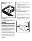
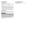
VIII. FILTERS
This unit is provided with 6 - 2" x 18" x 18" [51mm x 457 mm x
457 mm] disposable filters. When replacing filters, ensure they
are inserted fully to the back to prevent bypass.
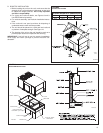
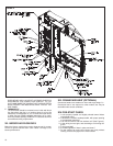
VIX. CONVERSION PROCEDURE
DOWNFLOW TO HORIZONTAL
1. Remove the screws and covers from the outside of the
supply and return sections.
2. Install the covers over the bottom supply and return open-
ings, painted side up inserting the leading flange under the
bracket provided. Place the back flange to the top of the
front bracket provided. See Figure 11.
3. Secure the return and supply cover to the front bracket with
one (1) screw.
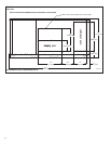
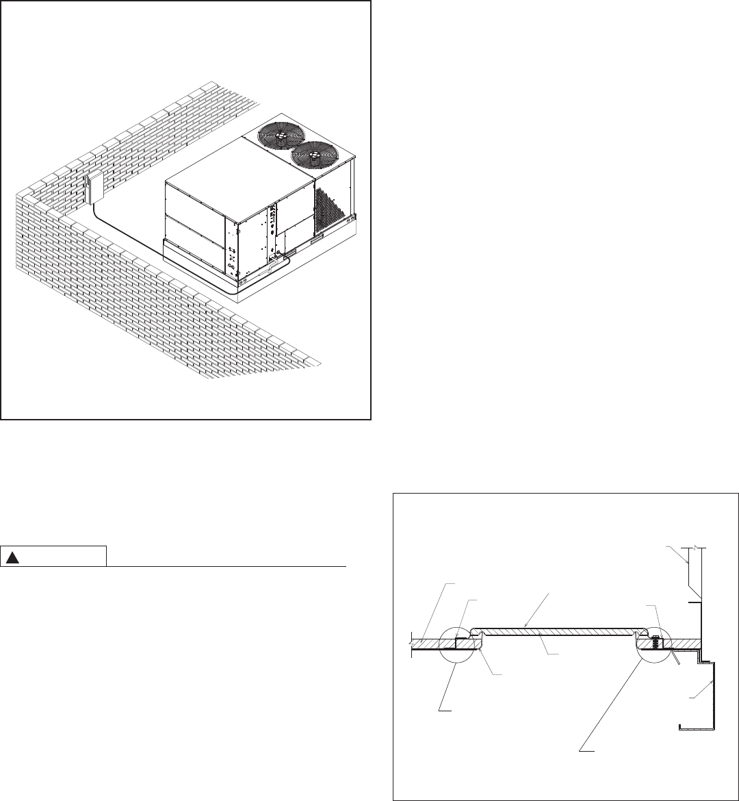
F
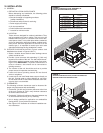
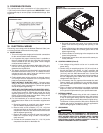
IGURE 10
F
LAT ROOFTOP INSTALLATION, ATTIC OR DROP CEILING
DISTRIBUTION SYSTEM. MOUNTED ON ROOFCURB.
C
URB MUST BE LEVEL
WARNING
!
A
1112-03
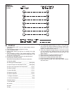
FIGURE 11
COVER GASKET DETAIL
A0725-01
REAR PANEL
FRONT BRACKET
SUPPLY OR RETURN COVER
INSULATION
BACK
BRACKET
INSULATION
BASE PAN
BASE RAIL
NOTE: COVER SLIDES
UNDER BACK
BRACKET FLANGE.
NOTE: COVER FITS ON
TOP OF FRONT
BRACKET FLANGE.
14