


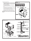
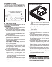
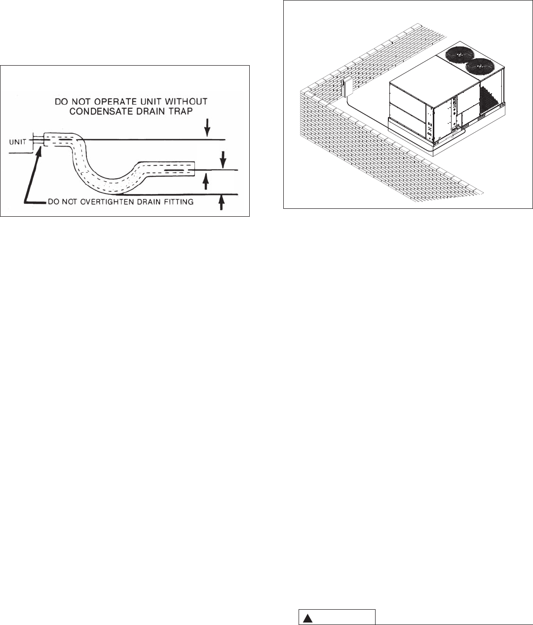
X. CONDENSATE DRAIN
The condensate drain connection of the evaporator is
1" [25.4 mm] nominal female pipe thread. IMPORTANT: Install
a condensate trap to ensure proper condensate drainage. See
Figure 12.
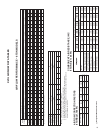
XI. ELECTRICAL WIRING
Field wiring must comply with the National Electrical Code (CEC
in Canada) and local ordinances that may apply.
A. POWER WIRING
1. This unit incorporates single-point electrical connections
for the unit and electric heat accessory.
2. It is important that proper electrical power is available to
the unit. Voltage should not vary more than 10% from the
values marked on the unit rating plate. Phase voltages
must be balanced within 3%.
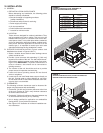
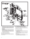
3. Install a branch circuit disconnect within sight of the unit.
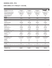
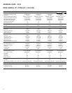
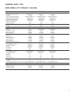
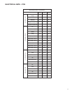
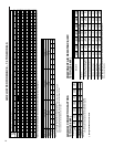
Use the unit rating plate or RLNL-B Electrical Data to
determine the required size.
4. The branch circuit wire must be sized in accordance with
the National Electrical Code (C.E.C. in Canada) and local
ordinances that may apply using the minimum circuit
ampacity found on the unit rating plate.
5. Field-installed power wiring must be run through ground-
ed rain-tight conduit attached to the unit power entry
panel and connected as follows:
UNITS WITHOUT ELECTRIC HEAT - Connect power
wiring to the power terminal block located on the left side
of the electric heat compartment. Connect the ground
wire to the adjacent ground lug.
UNITS WITH FACTORY INSTALLED ELECTRIC HEAT -
Connect power wiring to the power terminal block located
on the electric heater kit. Connect the ground wire to the
adjacent ground lug. DO NOT connect aluminum wiring
directly to the electric heater terminal block. Wiring to the
unit contactors is factory-connected.
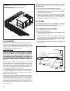
6. For field installation of an electric heater kit, follow the
instructions below. Refer to the information supplied with
the kit.
a. Removing screws as required, open heater access
door and detach adjacent power entry panel.
b. Remove wires to unit contactor (1L1, 1L2, 1L3) from
unit terminal block on the left side of the electric heat
compartment. Remove and discard the terminal block
and the adjacent ground lug.
c. Remove the heater kit block-off panel and install the
heater kit in its place using 9 of the 12 screws previ-
ously removed.
d. Connect the unit contactor wires (1L1, 1L2, 1L3) to the
compressor fuse block on the heater kit.
e. Re-install the power entry panel & run conduit and the
proper size field wiring through the opening in the
panel.
f. Connect field wiring to the power terminal block located
on the electric heater kit. Connect ground wire to the
adjacent ground lug.
g. Connect heater kit control plug to the receptacle on the
control wiring harness.
h. Close heater access door and secure with screws pre-
viously removed.
B. CONTROL WIRING (Class II)
1. Low voltage wiring should not be run in conduit with
power wiring.
2. Control wiring is routed through the 7/8" [22 mm] hole in
the unit side panel. See Figure 14. Use a minimum #18
AWG thermostat wire. For wire lengths exceeding 50'
[15.24 m] use #16 AWG thermostat wire. Connect the
control wiring to the low voltage terminal block located on
the unit integrated control. Route wires under the control
voltage shield. See Figure 14.
3. It is necessary that only approved thermostats be used.
Please contact your distributor for part number informa-
tion. See thermostat specification catalog for recommend-
ed thermostat.
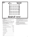
4. Figure 15 shows representative low voltage connection
diagrams. Read your thermostat installation instructions
for any special requirements for your specific thermostat.
C. INTERNAL WIRING
1. A diagram of the internal wiring of this unit is located on
the inside of the control access panel and in this manual.
If any of the original wiring must be replaced, the wire
gauge and insulation must be the same as original wiring.
Transformer is factory-wired for 220 volts on 200/220 volt
models and must be changed for 200-volt applications.
See unit wiring diagram for 200-volt wiring.
D. GROUNDING
THE UNIT MUST BE PERMANENTLY GROUNDED. A
GROUNDING LUG IS PROVIDED IN THE ELECTRIC
HEAT ACCESS AREA FOR A GROUND WIRE. FAILURE
TO GROUND THIS UNIT CAN RESULT IN FIRE OR
ELECTRICAL SHOCK CAUSING PROPERTY DAMAGE,
SEVERE PERSONAL INJURY OR DEATH.
F
IGURE 12
C
ONDENSATE DRAIN
FIGURE 13
B
RANCH CIRCUIT DISCONNECT LOCATION
3”
[76 mm]
3”
[
76 mm]
WARNING
!
15