


45
Heat & Glo •
TRUE-36, TRUE-42, TRUE-50 • 2282-900 Rev. D • 8/12
12
12
Electrical Information
A. Wiring Requirements
NOTICE: This appliance must be electrically wired
and grounded in accordance with local codes or, in the
absence of local codes, with National Electric Code
ANSI/NFPA 70-latest edition or the Canadian Electric
Code CSA C22.1.
• Wire the appliance junction box to 110-120 VAC. This is
required for use of optional accessories (standing pilot
ignition) or proper operation of the appliance (IntelliFire
Plus
TM
ignition).
• A 110-120 VAC circuit for this product must be protected
with ground-fault circuit-interrupter protection, in
compliance with the applicable electrical codes, when
it is installed in locations such as in bathrooms or near
sinks.
• Low voltage and 110 VAC voltage cannot be shared
within the same wall box.
WARNING! Risk of Shock or Explosion! DO NOT wire
110V to the valve or to the appliance wall switch. Incorrect
wiring will damage controls.
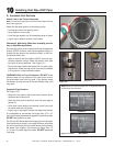
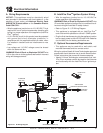
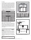
B. IntelliFire Plus
TM
Ignition System Wiring
• Wire the appliance junction box to 110-120 VAC for
proper operation of the appliance.
WARNING! Risk of Shock or Explosion! DO NOT wire
IPI controlled appliance junction box to a switched circuit.
Incorrect wiring will override IPI safety lockout.
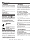
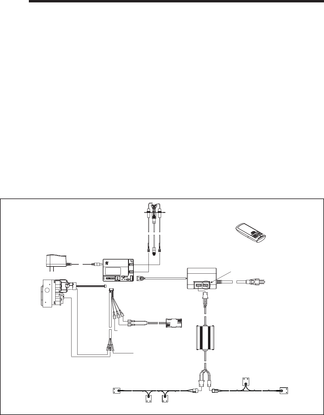
• Refer to Figure 12.1, IPI Wiring Diagram.
• This appliance is equipped with an IntelliFire Plus
TM
control valve which operates on a 6 volt/1.5 AMP system.
• Plug the 6 volt transformer plug into the appliance junction
box to supply power to the unit OR install 4 AA batteries
(not included) into the battery pack before use.
C. Optional Accessories Requirements
• This appliance may be used with a wall switch, wall
mounted thermostat and/or a remote control.
Wiring for optional Hearth & Home Technologies approved
accessories should be done now to avoid reconstruction.
Follow instructions that come with those accessories.
• Hearth & Home Technologies recommends that Intel-
liFire Plus
TM
wireless controls be used for their features
and functionality with the IntelliFire Plus
TM
ignition sys-
tem.
Figure 12.1 IPI Wiring Diagram
LED CONTROL
TO JUNCTION
BOX (110V)
MODULE
I
S
FLAME
SENSE
IGNITER
RC300 4.5V DC
(AA X 3)
TO JUNCTION
BOX 110VAC
AUX2 NOT USED
PROTECTIVE COVER INCLUDED
GROUND
ORANGE
(PILOT)
GREEN
(MA
IN)
BROWN
BLACK
RED
BATTERY PACK
6V DC
FLAME
MODULATION
AUX300 MODULE
AUX 1
AUX 2
FRONT EMBER LIGHTING (X 3)
REAR ACCENT LIGHTING (X 2)
ORANGE
WHITE