


Page 10
August 1, 2008
Heat & Glo · Tiara I B & Tiara II B · 7010-149M
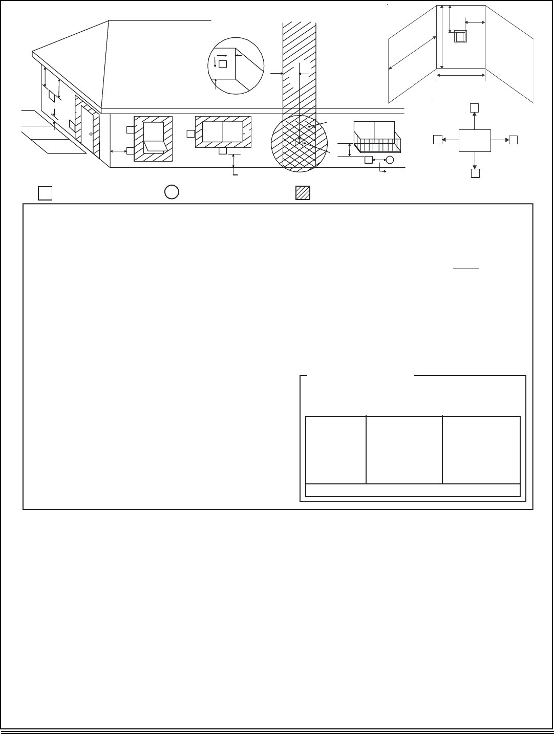
Figure 4.4
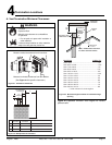
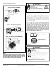
CAUTION: IF EXTERIOR WALLS ARE FINISHED WITH VINYL
SIDING, IT IS SUGGESTED THAT A VINYL PROTECTOR KIT BE
INSTALLED.
V
= VENT TERMINAL
X
= AIR SUPP L Y INLET = ARE A WHERE TERMINA L IS NOT PERMITTED
A = 12 inche s ............. clearances above grade , veran-
da, porch, deck or balcon y
B = 12 inche s ............ clearances to window or doo r
that may be opened, or to per -
manen t ly closed windo w . ( G lass )
D * = 12 inche s ............. ver t ical clearance t o unven t ila t -
ed s o f f i t o r t o v en t ila t ed s o f f i t lo -
c a t ed above t he t ermina l
*30 inche s ............ f o r v in y l c lad s o ff i ts and belo w
electrical servic e
F = 9 inche s ............. . c l earance to outside corne r
G = 6 inche s ............... c lea r an c e t o in s ide c o r ne r
H = 3 f t. (Canada ) ..... . not to be ins t alled above a ga s
meter/regulator assembly within 3
feet (90cm) horizon t ally from th e
center-line of the regulato r
I=3ft.
....... clearance to gas service regula -
tor vent outle t
J = 9 inches (U.S.A. )
12 inches (Canada ) clearance to non-mechanical ai r
supply inle t t o building or t h e
combustion air inlet to any othe r
applianc e
K = 3 ft. (U.S.A. )
6 f t. (Canada ) ......... clearance to a mechanica l
(powered) a i r s uppl y inle t
L* * = 7 ft . ......................... clearance above pave d
sidewalk or a paved drivewa y
located on publi c propert y
M** * = 18 inche s .............. clearance under veranda ,
porch, deck, balcony or over -
han g
42 inche s .............. viny l
(S ee N ot e 1 )
(S ee N ot e 1 )
S = 6 inche s ................. clearance from sides o f
electrical servic e
T = 12 inche s ................ c lea r a n c e abo v e ele ctr i c a l
servic e
(S ee N ot e 3 )
(S ee N ot e 3 )
_____________________________________________________________________
_____________________________________________________________________
_____________________________________________________________________
_____________________________________________________________________
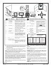
Q
MI N
R
MA X
1 ca p 3 f ee t 2 x Q
ACTU A L
2 ca p s 6 fee t 1 x Q
ACTU A L
3 ca p s 9 fee t 2/3 x Q
ACTU A L
4 ca p s 12 fee t 1/2 x Q
ACTU A L
N = 6 inche s ................. non-vinyl sidewall s
12 inche s ............... v in y l sidewall s
P = 8 ft .
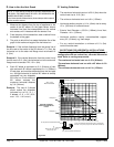
Alcove Application s
* * a vent shall not terminate directly above a sidewalk or p ave d
driveway which is located between two single family dwellings an d
** * onl y pe rm i tt ed i f v e r anda , po rc h , de ck o r bal c on y i s f ull y open o n
a minimum o f 2 sides benea t h t he f loo r , or mee t s No t e 2 .
NOTE 1: On private property where termination is less than 7 feet above
a sidewalk, drivewa y , deck, porch, veranda or balcon y , use of a listed
cap is suggested. (See vents components pages.)
NOTE 2: T ermination in an alcove space (spaces only open on one side
and withat an overhang) are permitted with the dimensions specified for
vinyl or non-vinyl siding and so f fits. 1. There must be at least 3 feet
minimum between termination caps. 2. All mechanical air intakes within
10 feet of a termination cap must be a minimum of 3 feet below the
termination cap. 3. All gravity air intakes within 3 feet of a termination cap
must be a minimum of 1 foot below the termination cap.
NOTE 3: Location of the vent termination must not interfere with access
t
o
th
e
e
l
ec
tri
ca
l
se
rvi
ce
.
NOTE: Local codes or regulations may require di f ferent
clearances.
NOTE: T ermination caps may be hot. Consider their proximity to
doors or other tra f fic areas .
W ARNING: In the U.S.: V ent system termination is NOT permitted
in screened porches. Y ou must follow side wall, overhang and
ground clearances as slated in the instructions.
In Canada: V ent system termination is NOT permitted in screened
porches. V ent system termination is permitted in porch areas with
two or more sides open. Y ou must follow side wall, overhang and
ground clearances as slated in the instructions.
Heat & Glo assumes no responsibility for the improper performance
of the appliance when the venting system does not meet these
requirements.
serves both dwellings.
(See Note 2)
Electrical
Service
V
S
V
S
V
T
D*
V
D
E
B
L
v
v
v
v
v
v
v
v
B
B
A
H
M
X
J or K
I
A
G
F
U.S.
(3 FT)
B
M
N
P
R
Q
R
MAX
= (2 / # termination caps) x Q
ACTUAL
Q
MIN
= # termination caps X 3
................