


Heat & Glo • SL-750TRS-IPI-E, SL-550TRS-IPI-E, SL-350TRS-D, SL-350TRS-IPI • 2120-900 Rev. D • 6/0744
5
6
7
8
9
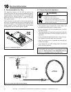
10
3
4
5
12
11
10
9
8
7
6
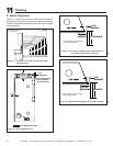
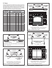
TOP OF HOOD OR FIREPLACE OPENING
4
12
13
11
32
CEILING
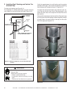
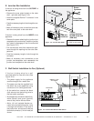
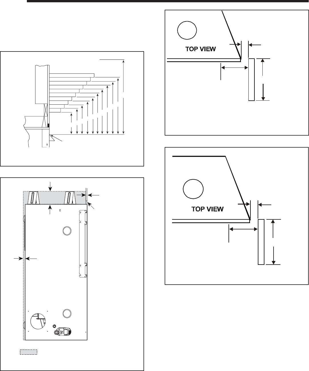
A. Mantel Projections
Figure 11.1 shows the minimum vertical and correspond-
ing maximum horizontal dimensions of appliance mantels
or other combustible projections above the top front edge
of the appliance.
11
11
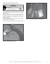
Finishing
Figure 11.1 Clearances to mantels or other combustibles
above appliance
All measurements
are in inches
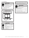
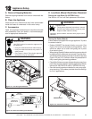
1/2 in.
SHEETROCK
3-1/2 in.
1/2 in.
NON-COMBUSTIBLE ZONE
NON-COMBUSTIBLE
BOARD SHIPPED
WITH APPLIANCE
Figure 11.2 Non-Combustible Zone
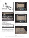
3 FT. MAXIMUM
2-7/8 IN.
MINIMUM
1/2 IN.
MINIMUM
Note: Clearance from opening
to perpendicular wall.
Figure 11.3 Clearances to Mantel Legs or Wall Projections
(Acceptable on both sides of opening.)
5-3/8 IN.
MINIMUM
3 IN.
MINIMUM
UNLIMITED
Note: Clearance from opening
to perpendicular wall.
Figure 11.4 Wall Projection (Acceptable on one side of opening.)
Î
Î