


Heat & Glo • SL-750TRS-IPI-E, SL-550TRS-IPI-E, SL-350TRS-D, SL-350TRS-IPI • 2120-900 Rev. D • 6/0734
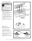
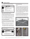
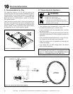
D. Assembly of Vent Sections (SL pipe)
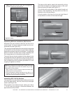
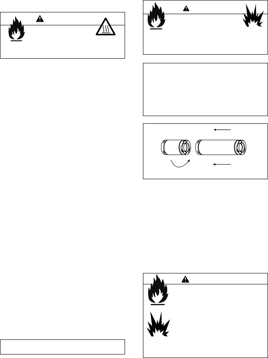
Continue Adding Vent Components
• Continue adding vent components, locking each suc-
ceeding component into place.
• Ensure that each succeeding vent component is securely
fi tted and locked into the preceding component.
• 90° elbows may be installed and rotated to any point
around the preceding component’s vertical axis. If an
elbow does not end up in a locked position with the
preceding component, attach with a minimum of two (2)
sheet metal screws.
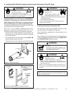
Figure 8.12 Adding Venting Components
Install Support Brackets
For Horizontal Runs - The vent system must be supported
every fi ve (5) feet of horizontal run by a horizontal pipe
support.
To install support brackets for horizontal runs:
• Place the pipe supports around the vent pipe.
• Nail the pipe supports to the framing members. For Ver-
tical Runs - The vent system must be supported every
eight (8) feet (2.4 m) above the appliance fl ue outlet by wall
brackets. To install support brackets for vertical runs:
• Attach wall brackets to the vent pipe and secure the wall
bracket to the framing members with nails or screws.
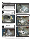
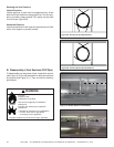
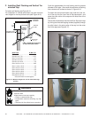
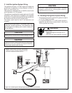
Attach the First Vent Component to Starting Collars
To attach the fi rst vent component to the starting collars
of the appliance:
• Lock the vent components into place by sliding the con-
centric pipe sections with four (4) equally spaced interior
beads into the appliance collar or previously installed
component end with four (4) equally spaced indented
sections.
• When the internal beads of each outer pipe line up, ro-
tate the pipe section clockwise about one-quarter (1/4)
turn (see Figure 8.13). The vent pipe is now locked
together.
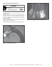
• Slide the ceramic fi ber pad over the fi rst vent section
and place it fl ush to the appliance. This will prevent cold
air infi ltration. High temp caulk may be used to hold the
part in place. Continue to add vent components.
Fire Risk
Exhaust Fumes Risk
Impaired Performance of Appliance
• Ensure vent components are locked together correctly.
• Pipe may separate if not properly joined.
Fire Risk.
Explosion Risk.
Combustion Fume Risk.
Use vent run supports per installation
instructions.
Connect vent sections per installation
instructions.
• Maintain all clearances to combustibles.
• Do NOT allow vent to sag below
connection point to appliance.
• Maintain specifi ed slope (if required).
Improper support may allow vent to sag or separate.
WARNING
WARNING
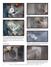
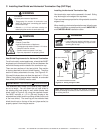
Note: When installing a vent system with an HRC
termination cap, all pipe system joints shall be sealed using
a high-temperature silicone sealant.
• Apply a bead of silicone sealant inside the female outer
pipe joint prior to joining sections.
• Only outer pipes are sealed, sealing the inner fl ue is not
required. All unit collar, pipe, slip section, elbow and cap
outer fl ues shall be sealed in this manner.
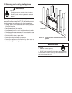
Commercial, Multi-family (Multi-level exceeding two
stories), & High-Rise Applications
For Installation into Commercial, multi-family (multi-level ex-
ceeding two stories) or high-rise applications: All pipe joints
must be sealed with high temperature silicone, including the
slip section that connects directly to the horizontal termina-
tion cap.
• Apply a bead of silicone sealant inside the female outer
pipe joint prior to joining sections. See Figure 8.1
• Only outer pipes are sealed. Do not seal the inner fl ue.
All unit collar, pipe, slip section, elbow and cap outer fl ues
shall be sealed in this manner, unless otherwise stated.
Fire Risk
Explosion Risk
If slip section seals are broken during the
removal of the termination cap, gas will leak and
a fi re or explosion may occur.
Do not break silicone seals on slip sections.
WARNING
Note: The end of the pipe sections with the lances/tabs on it
will face toward the appliance.