


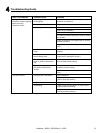

21
7
7
Installation of Fireplace
CAUTION! Risk of Cuts/Abrasions. Wear protective
gloves and safety glasses during installation. Sheet metal
edges are sharp.
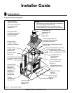
A. Things to Consider
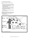
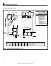
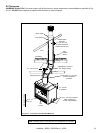
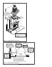
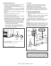
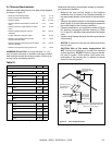
• Location of chimney air kit (see Figure 7.4)
• Location(s) of outside air kit
• Electrical connections and/or wall switch
• Gas line piping
B. Position the Fireplace
• Place the fi replace on a continuous fl at surface.
• Follow framing instructions in Section 6.
WARNING! Risk of Fire! Prevent contact with sag-
ging, loose insulation.
• DO NOT install against vapor barriers or exposed
insulation.
• Secure insulation and vapor barriers.
• Provide minimum air space clearances at the sides
and back of the fi replace assembly as outlined in
Section 6.
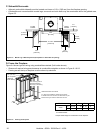
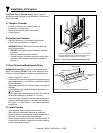
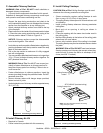
Protective metal strips are placed 2 in. (51 mm) under the
front of the fireplace and must extend beyond the front
and sides of fireplace opening by 2 in. (51 mm).
1 in. (25 mm)
overlap
Figure 7.1 Position the Protective Metal Hearth Strips
C. Place Protective Metal Hearth Strips
WARNING! Risk of Fire! Protective metal hearth strips
MUST be installed. DO NOT cover metal strips with com-
bustible materials. Sparks or embers may ignite fl ooring.
• Refer to Figures 7.1 and 7.2.
• Locate the two protective metal hearth strips measuring
approximately 26 in. x 4 in. (660 mm x 102 mm) included
with this fi replace.
• Slide each metal strip 2 in. (51 mm) under front edge of
fi replace.
• Overlap strips in the middle of fi replace opening by 1 in.
(25 mm) minimum..
• Metal strips must extend beyond the front and sides of
the fi replace opening by at least 2 in. (51 mm).
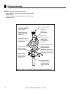
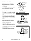
• Protect the front of a platform elevated above the hearth
extension with metal strips (not included with fi replace)
per Figure 7.2. See Section 11 for hearth extension
instructions.
D. Level Fireplace
• Level fi replace side-to-side and front-to-back.
• Shim with non-combustible material as necessary.
• Secure fi replace to framing with nailing fl anges with a
minimum of two fasteners per nailing fl ange.
• Check fi replace opening for square to ensure proper fi t
of glass doors. Measure diagonals of fi replace opening
to make sure they are equal.
Raised Platform
Floor
2 in.
(51 mm)
1 in. (25 mm) min.
overlap
2 in.
(51 mm)
Top piece must overlap
bottom piece
Figure 7.2 Protect the Front of an Elevated Platform
Heatilator • SC60 • 32838 Rev X • 10/08