


Hearth & Home Technologies - Colville
1445 North Highway, Colville, WA 99114-2124
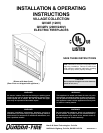
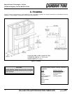
VILLAGE COLLECTION ELECTRIC FIREPLACE
7
09/03
4030-240 Rev F
Note: This appliance must be electrically wired and grounded
in accordance with local codes or, in the absence of local codes,
with National Electric Code ANSI/NFPA 70-latest edition or
the Canadian Electric Code, CSA C2.1 as appropriate.
Note: Optional Accessories Requirements: Wiring for optional
accessories should be done now to avoid reconstruction.
CAUTION:
Label all wires prior to disconnection when servicing
controls. Wiring errors can cause improper and dangerous
operation. Verify proper operation after servicing.
F. WIRING
All wiring to be done by a qualified electrician.
Use appropriate wire to meet local and national
codes for rated power consumption.
1. Power Supply Wiring
a. 110/120VAC Wall Outlet Installation
1) The appliance is wired from factory with a polarized plug.
2) For ease of electrical hook up, you may wish to install the appliance near an existing outlet. A 15 amp, 120 volt circuit is
required. A dedicated circuit is preferred but not essential in all cases. A dedicated circuit will be required if, after installation,
the circuit trips or fuse blows on a regular basis when the appliance is operated. Additional appliances on the same circuit
may exceed the current rating of the circuit breaker.
3) Before plugging appliance into wall outlet, make sure all control switches are in the OFF position. To access the controls,
lift up on the lower grille panel and rotate it forward.
4) If the power cord is not being used, go to Step 1b below. If the cord does not reach the outlet, a No. 16-AWG minimum wire
size extension cord rated for a minimum of 1875 watts may be used.
b. 110/120VAC Hardwire Installation (Minimum 14 gauge two conductor wire, non-metallic sheathing with ground.)
1) Turn off circuit breaker.
2) Remove cover plate located on the right side of appliance.
3) Disconnect black (L
1
) and white (L
2
) wires between the appliance and plug. Remove the power cord from the cover plate.
Remove the electrical knockout and install the cable clamp (not provided) onto the cover plate. Remove the connectors
on the wires from the appliance and strip them back ½.
4) Feed 8 of service wire through cable clamp and secure.
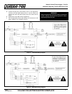
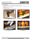
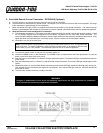
5) Connect black (L
1
) and white (L
2
) wires of the appliance to the black and white wires from the service. Connect green
(ground) wire from appliance to the ground of the service. See Figure 3.
6) Wall switch wiring (see below) is to be done at this time.
7) Replace the cover plate onto the appliance.
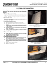
8) Remove the protective cover by cutting the tape located on the outer perimeter and follow Section H. Final Installation on
setting up the appliance.
c. HT240V Heater Kit and 208/220/240VAC Hardwire Installation (Minimum 14 gauge three conductor wire, non-metallic
sheathing with ground.)
1) Turn off circuit breaker.
2) Remove cover plate located on the right side of appliance.
3) For HT240V installation only, disconnect black (L
1
) and white (L
2
) wires between the appliance and plug. Remove the
power cord (HT240V only) from the cover plate.
4) Remove the electrical knockout and install the cable clamp onto the cover plate. Remove the connectors on the wires
from the appliance and strip them back ½.
5) Feed 8 of service wire through cable clamp (not provided) and secure.
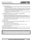
6) Connect black (L
1
), white (L
2
) and red (L
3
) wires of the appliance to the black, white and red wires from the service.
Connect green (ground) wire from appliance to the ground of the service. See Figure 4.
7) Wall switch wiring (see below) is to be done at this time.
8) Replace the cover plate onto the appliance.
9) Remove the protective cover by cutting the tape located on the outer perimeter and follow Section H. Final Installation on
setting up the appliance.
2. Wall Switch Wiring (24VAC) *Do not connect wires to 120/208/240VAC*
(hardwired appliances only)
a. Turn off circuit breaker.
b. Remove cover plate located on the right side of appliance.
c. Feed 8 of wire for the wall switch through the cable clamp and secure. Low voltage wire can be used for the wall switch
connection. It is recommended to only go 10 from the appliance to the wall switch.