


20
B
A
9 3/4 in.
[248 mm]
12 in.
[305 mm]
12 in.
[305 mm]
11 1/4 in.
[286 mm]
FLUSH
FRONT
4 in.
[102 mm]
BRICK
FRONT
50° angle
39° angle
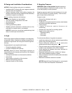
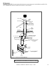
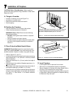
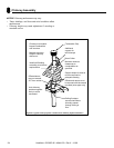
D. Frame the Fireplace
Figure 6.4 shows typical framing using combustible materials (2x4 lumber shown).
• Observe all required air space clearances to combustible materials as shown in Figure 6.1 & 6.2.
• Framing across the top of fi replace must be above top standoffs.
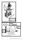
B
C
A
2 in. (51 mm)
min. air space
clearance
from chimney.
Note: Framing must be
extended straight up,
all the way to the ceiling.
Header MUST NOT be notched!
D
D = extra space needed for outside air connection.
If outside air duct has no bend, this dimension may be
reduced as long as minimum clearances are met.
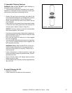
Figure 6.4 Framing the Fireplace
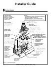
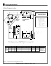
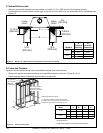
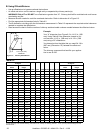
C. Sidewalls/Surrounds
• Adjacent combustible sidewalls must be located a minimum of 12 in. (305 mm) from the fi replace opening.
• Combustible and noncombustible mantel legs, surrounds and stub walls may be constructed within the gridded area,
Figure 6.3.
Figure 6.3 Mantel Leg or Wall Projections (Acceptable on both sides of opening)
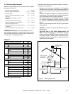
Model #
A
Fireplace
Opening
B
Outside
Dimensions
EL36
in. 36 41
mm 914 1041
EL42
in. 42 47
mm 1067 1194
Heatilator • EL36/EL42 • 4044-132 • Rev V • 11/08
Model A B* C** D
EL36
in. 42 21 1/2 39 3/4 8
mm 1067 546 1010 203
EL42
in. 48 21 1/2 39 3/4 8
mm 1219 546 1010 203
* If interior of chase will be drywalled, add the thickness to
this measurement.
** Adjust header height for a raised fl oor under fi replace.