


Quadra-Fire • Columbia Bay Insert • 7002-109 Rev. H • 10/0812
If the pressure is not suffi cient, ensure:
• The piping used is large enough.
• The supply regulator is adequately adjusted.
• That the total gas load for the residence does not
exceed the amount supplied.
The supply regulator (the regulator that attaches directly
to the residence inlet or to the propane tank) should supply
gas at the suggested input pressure listed above. Contact
the local gas supplier if the regulator is at an improper
pressure.
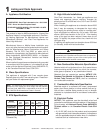
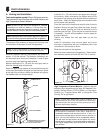
D. Gas Pressures
Proper input pressures are required for optimum appli-
ance performance. Gas line sizing requirements need to
be made following NFPA54.
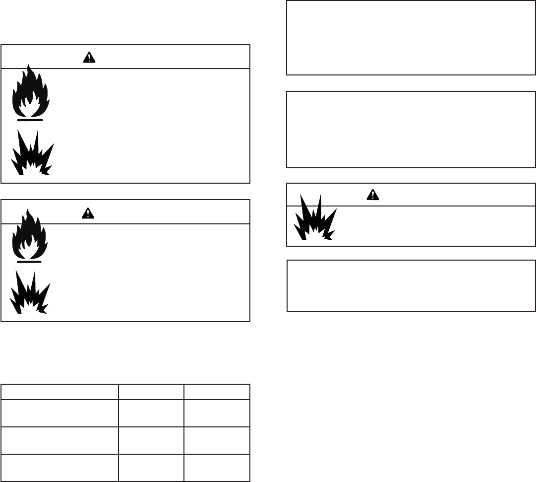
Fire Risk.
Explosion Hazard.
High pressure will damage valve.
• Disconnect gas supply piping BEFORE
pressure testing gas line at test pressures
above 1/2 psig.
• Close the manual shutoff valve BEFORE
pressure testing gas line at test pressures
equal to or less than 1/2 psig.
Verify inlet pressures.
• High pressure may cause overfi re condition.
• Low pressure may cause explosion.
• Verify minimum pressures when other
household gas appliances are operating.
Install regulator upstream of valve if line
pressure is greater than 1/2 psig.
Pressure requirements for appliance are shown in the
table below. Minimum pressures must be met when other
household gas appliances are operating.
WARNING
WARNING
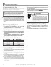
Pressure Natural Gas Propane
Minimum inlet pressure
4.5 inches
w.c.
11.0 inches
w.c.
Maximum inlet gas pressure
7.0 inches
w.c.
14.0 inches
w.c.
Manifold pressure
3.5 inches
w.c.
10.0 inches
w.c.
Leak test all gas line joints and the gas control valve prior
to and after starting the appliance.
Before making the gas connection, ensure that the
appliance you are installing is designed for the type of
gas being supplied. This information can be found on the
ratings label under the appliance. If the appliance has
been converted to propane (LP), the valve cover should
have a label stating that the appliance has been converted
to propane.
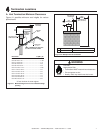
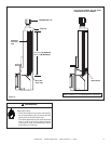
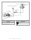
Connect the gas line at the 3/8 in. (10 mm) pipe connector
on the valve at the back of appliance. We recommend
connecting the appliance with an approved flex gas line.
If flex gas lines are not approved in your area, you must
connect a hard pipe to the gas hookup.
You must supply a manual shut-off valve in a visible
location within 3 ft. (914 mm) of the appliance.
Ensure that gas line does not come in contact with outer
wrap of appliance. Follow local codes.
Incoming gas line should be piped into the valve
compartment and connected to the 1/2 inch connection
on the manual shutoff valve.
Note: Have the gas supply line installed in accordance
with local building codes, if any. If not, follow ANSI
223.1. Installation should be done by a qualifi ed installer
approved and/or licensed as required by the locality. (In
the Commonwealth of Massachusetts installation must be
performed by a licensed plumber or gas fi tter).
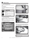
E. Gas Connection
Note: A listed (and Commonwealth of Massachusetts ap-
proved) 1/2 inch (13 mm) T-handle manual shut-off valve and
fl exible gas connector are connected to the 1/2 inch (13 mm)
control valve inlet.
• If substituting for these components, please consult
local codes for compliance.
Gas Leak Risk
• Support control when attaching pipe to
prevent bending gas line.
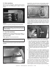
Note: The gap between supply piping and gas access hole
may be caulked with high temperature caulk or stuffed with
non-combustible, unfaced insulation to prevent cold air
infi ltration.
WARNING