


Heatilator • Caliber CNXT Series • 4047-132 Rev U • 11/0854
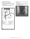
Wiring the Wall Switch
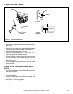
• Install the provided control wire from the fi replace to the
switch location. (Control wire for Heatilator products is
supplied with the fi replace).
NOTICE: Do not to stress the wire around tight or sharp
corners. Do not run the control wire adjacent to existing
or future phone, data, cable, or electrical lines. The
wire should not come into contact with any part of the
fi replace exterior with the exception of where it exits the
outer wrap.
ORANGE
GREEN
GROUND
BLACK
WHITE
BLACK
AUX
CONNECTION
BLACK
BLACK
GROUND PIGTAIL
GREEN
FLAME HIGH/LOW
AC
PLUG
ORANGE
ORANGE
RED
RED
FLAME ON
ADAPTER WIRES
FLAME
SOLENOID
IPI
VALVE
IPI
MODULE
BROWN
BLACK
FAN
CONNECTION
YELLOW
YELLOW
FRONT VIEW
REAR VIEW
RED
GREEN
YELLOW OR
WHITE
FAN THERMOSTAT
3V DC
BROWN
BROWN
RED
BLACK
BATTERIES
BLACK
RED
KCALB
DER
1
2
3
4
5
6
7
8
* May be labeled as “W” or “Y”.
*
deR
)E
L
A
MEF/
E
LAM(
deR
)ELAMEF/ELAM(
*
TEMPERATURE
SENSOR SWITCH
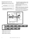
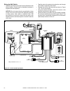
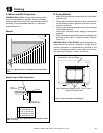
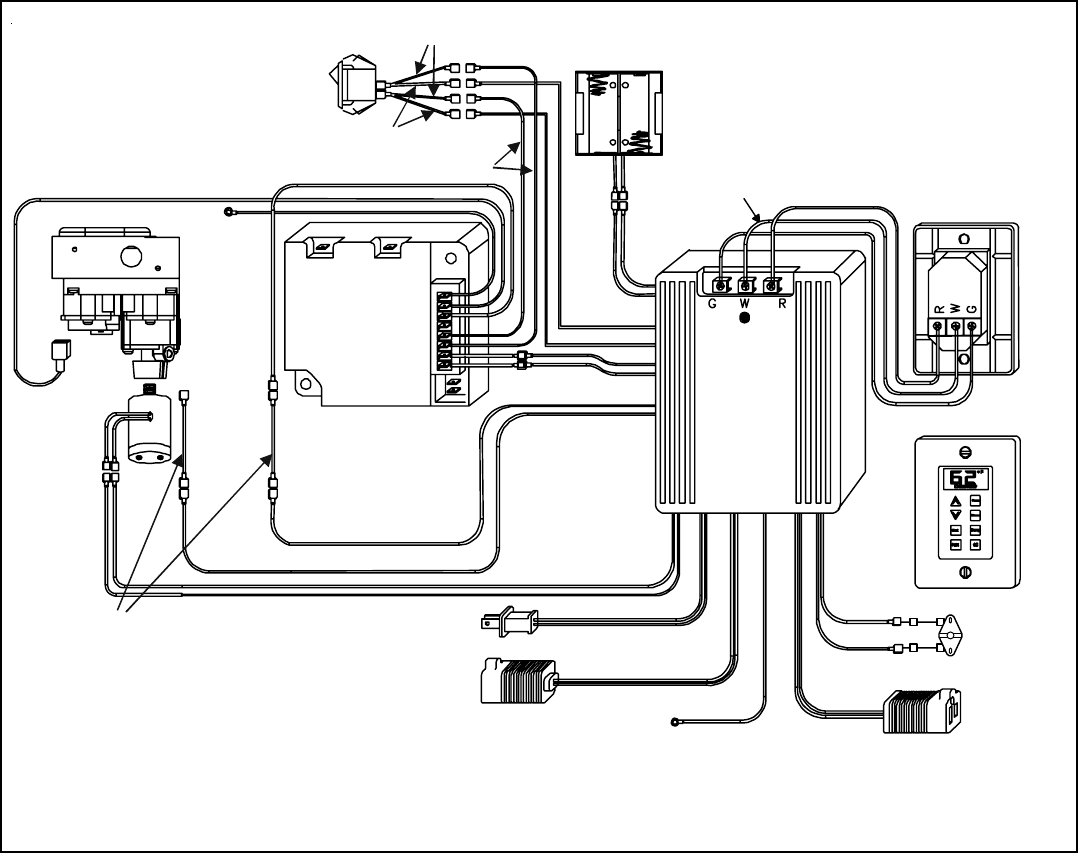
Figure 12.2 Intellifi re (IPI) Wiring Diagram
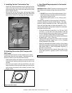
• Feed the wire to the electrical junction box and through
a provided or approved strain relief.
• Connect the wires to the terminals as shown in Figure
12.2. Do not over-tighten.
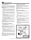
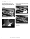
• Using the screws provided, mount the switch to the
electrical junction box right side up.
• Install provided cover plate using the screws provided.
Do not use a substitute cover even though it may fi t. The
provided one is specifi cally designed for the automatic
(thermostat) function of the unit.