


Heat & Glo • 8000TR-OAK, 8000TR-OAK-IPI, 8000TRLP-OAKIPI • 2057-900 Rev. P • 11/0842
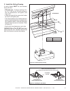
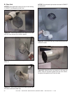
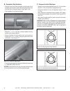
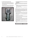
B. Assemble Slip Sections
• Slide the inner fl ue of the slip section into the inner fl ue of
the pipe section and the outer fl ue of the slip section over
the outer fl ue of the pipe section. See Figure 10.6.
• Slide together to the desired length.
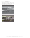
Figure 10.6 Slip Section Pilot Holes
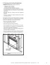
Figure 10.7 Screws into Slip Section
Pilot hole
Pilot hole
• Continue adding pipe as necessary following instructions
in “Assembling Pipe Sections.”
NOTICE: If slip section is too long, the inner and outer fl ues
of the slip section can be cut to the desired length.
• Maintain a 1-1/2 in. (38 mm) overlap between the slip
section and the pipe section.
• Secure the pipe and slip section with two screws no
longer than 1/2 in. (13 mm), using the pilot holes in the
slip section. See Figure 10.7.
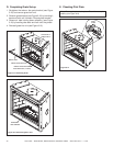
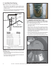
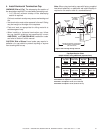
120º
Figure 10.8 Securing Vertical Pipe Sections
120º
Figure 10.9 Securing Horizontal Pipe Sections
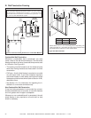
C. Secure the Vent Sections
• Vertical runs must be supported every 8 ft. (2.44 m) after
the 25 ft. (7.62 m) maximum unsupported rise.
• Horizontal sections must be supported every 5 feet
(1.52 m).
• Vent supports or plumbers strap (spaced 120º apart)
may be used to support vent sections. See Figures 10.8
and 10.9.
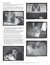
• Wall shield fi restops may be used to provide horizontal
support vent sections.
WARNING! Risk of Fire, Explosion or Asphyxiation!
Improper support may allow vent to sag and separate.
Use vent run supports and connect vent sections per in-
stallation instructions. DO NOT allow vent to sag below
connection point to appliance.