


Heat & Glo • 8000TR-OAK, 8000TR-OAK-IPI, 8000TRLP-OAKIPI • 2057-900 Rev. P • 11/0834
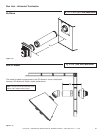
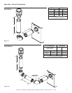
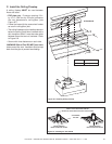
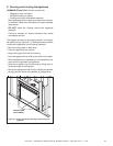
Figure 8.6 Wall Penetration
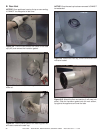
B. Wall Penetration Framing
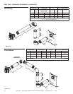
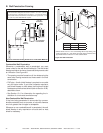
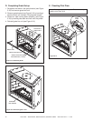
Figure 8.5 Horizontal Venting Clearances to Combustible Materials
3 IN. TOP
CLEARANCE
HEAT
SHIELD
HEAT
SHIELD
WALL
WALL
SHIELD
FIRESTOP
1 IN. CLEARANCE
BOTTOM SIDES
Note: Heat shields MUST overlap by a minimum of 1-1/2 in. (38 mm).
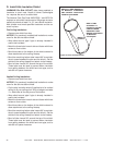
The heat shield is designed to be used on a wall 4 in. to 7-1/4 in. (102 mm
to 184 mm) thick. If wall thickness is less than 4 in. (102 mm) the existing
heat shields must be fi eld trimmed. If wall thickness is greater than 7-1/4
in. (184 mm) a DVP-HSM-B will be required.
Combustible Wall Penetration
Whenever a combustible wall is penetrated, you must
frame a hole for the wall shield fi restop(s). The wall shield
fi restop maintains minimum clearances and prevents cold
air infi ltration. See Figure 8.6.
• The opening must be framed on all four sides using the
same size framing materials as those used in the wall
construction.
• DVP pipe - A wall shield fi restop is required on one side
only on interior walls. If your local inspector requires a
wall shield fi restop on both sides, then both wall shield
fi restops must have a heat shield (refer to Section 16.B.)
attached to them.
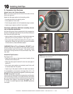
• See Section 10.J. for information for regarding the in-
stallation of a horizontal termination cap.
Non-Combustible Wall Penetration
If the hole being penetrated is surrounded by noncom-
bustible materials such as concrete, a hole with diameter
one inch greater than the pipe is acceptable.
Whenever a non-combustible wall is penetrated, the wall
shield fi restop is only required on one side and no heat
shield is necessary.
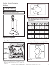
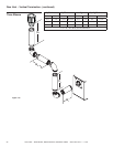
* Shows center of 10 in. x 12 in. vent framing hole for top venting. The
center of the hole is 1 inch above the center of the horizontal vent
pipe. With minimum vertical or 12 inch and 90º elbow.
A* B
Inches 29-7/8 45-1/8
Millimeters 759 1146
A*
12 in.
10 in.
B