


Heat & Glo • 6000GBV, 6000GBV-IPI • 2104-900 Rev. H • 11/0830
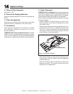
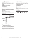
E. Electrical Service and Repair
WARNING! Risk of Shock! Label all wires prior to dis-
connection when servicing controls. Wiring errors can
cause improper and dangerous operation. Verify proper
operation after servicing.
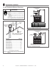
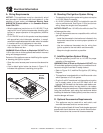
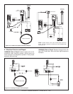
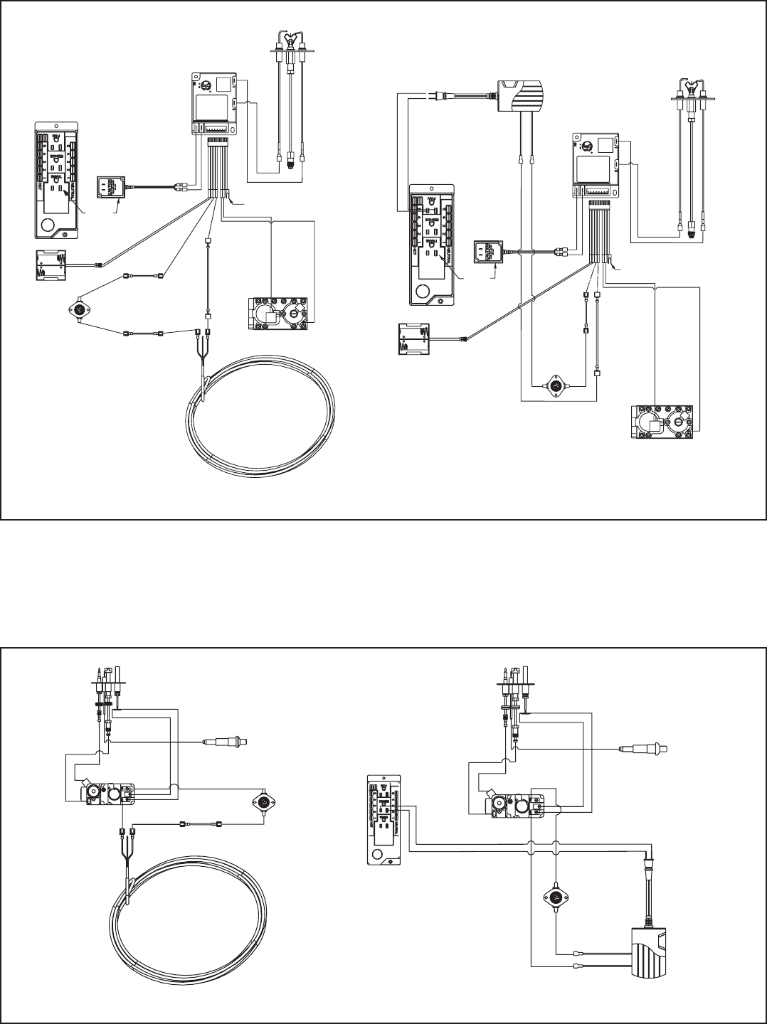
Figure 12.2 Intellifi re Pilot Ignition (IPI) Wiring Diagram
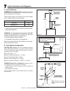
Figure 12.3 Standing Pilot Ignition Wiring Diagram
WARNING! Risk of Shock! Replace damaged wire with
type 105º C rated wire. Wire must have high temperature
insulation.
NOTE: 1. Ignition module, valve, pilot, and wall switch operate on
3 volts. 120 VAC is required at junction box unless equipped with
battery back-up.
RED
IGNITION
MODULE 3 VAC
GREEN
ORG
WHITE
INTERMITTENT
PILOT IGNITOR
VALVE
TRANSFORMER 3V
GROUND TO
FIREPLACE CHASSIS
BLACK
BROWN
IGNITION MODULE 3 VAC
INTERMITTENT
PILOT IGNITOR
THERMOSTAT WIRE ASSEMBLY
GROUND TO
FIREPLACE CHASSIS
TRANSFORMER
3 VAC
ORG
TEMP SENSOR
BATTERY PACK
ORG
GREEN
VALVE
BROWN
ORG
WHITE
TEMP SENSOR
BATTERY PACK
RED
BLACK
PLUG-IN
PLUG-IN
JUMPER W IRE
TO BROWN
REMOTE RECEIVER
S
I
THERMOCOUPLE
WHITE
WHITE
TEMP SENSOR
REMOTE
RECEIVER
VALVE
RED
PIEZO
VALVE
RED
TEMP SENSOR
PILOT
PILOT
THERMOCOUPLE
THERMOSTAT WIRE ASSEMBLY