


Heat & Glo • 6000GBV, 6000GBV-IPI • 2104-900 Rev. H • 11/08 25
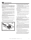
A. Installing Outside Air Kit Damper Assem-
bly
CAUTION! Risk of Cuts/Abrasions/Flying Debris.
Wear protective gloves and safety glasses during instal-
lation. Sheet metal edges are sharp.
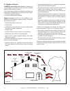
WARNING! Risk of Fire/Asphyxiation. DO NOT draw out-
side combustion air from:
• Wall, fl oor or ceiling cavity.
• Enclosed space such as an attic or garage.
• Close proximity to exhaust vents or chimneys.
Fumes or odor may result.
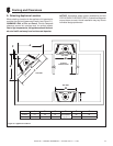
• Remove and discard cover plate or knockout from side
of appliance.
• Open air kit damper slightly.
• Locate door hinge toward back of appliance (see Figure
9.1).
9
9
Appliance Preparation
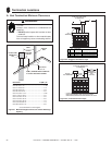
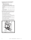
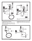
Figure 9.2 Outside Air Kit Installation
Figure 9.1 Damper Assembly and Handle
HANDLE
HINGE
DOOR
B. Gas and Electrical Connections
If applicable, ensure that gas and electrical connections are
installed at this time. Refer to Sections 11 (Gas Information)
and 12 (Electrical Information).
• Attach damper assembly to appliance using screws
provided (see Figure 9.2).
• Insert narrow end of handle through tab and into upper
slot of door.
• Check handle operation. Pull handle out to open, and in
to close.
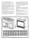
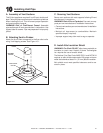
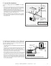
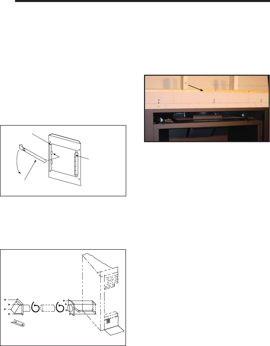
Figure 9.3 Non-combustible Board
Figure 9.3 Non-combustible Board
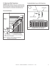
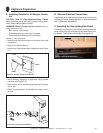
C. Installing the Non-combustible Board
The factory supplied non-combustible board spans the dis-
tance from the top of the fi replace to the center of the fram-
ing header. This board must be used. See fi gure 9.3.
HEADER
HEADER