


08/04 31072 Rev G 17
MHC36 AND MHR36 INSTALLATION INSTRUCTIONS
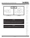
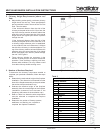
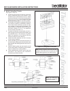
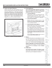
Figure 14 - Ceiling/Attic Construction
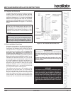
9. MH842 Ceiling/Roof Thimble
See Figures 14 and 15.
a. Locate the point where the chimney will exit the
roof by plumbing down to the center of the
chimney. Lay out, cut and frame a 14-1/2 in. square
opening (measured on the horizontal) through the
ceiling and roof structure. See Chapter 25 of the
Uniform Building Code for roof framing details.
b. The thimble must extend completely through the
roof structure shielding combustible materials.
Five location holes have been provided to allow
for a variety of ceiling/roof thicknesses. The
thimble extension is required when the ceiling/roof
thickness exceeds 12-1/2 in. The extension
should overlap the thimble 1 in.
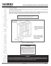
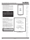
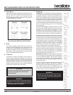
c. To attach the extension to the thimble, drill 1/8 in.
holes through the outer shield of the thimble using
the predrilled holes in the extension as guides.
Attach the extension to the thimble using the
screws provided with the extension.
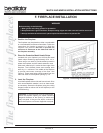
d. Install the thimble assembly and nail it securely
to the framing members.
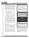
e. Center the flashing over the chimney and nail it to
the roof using the Stormguard nails provided. Keep
gaps between the flashing plate and the roof to a
minimum
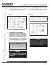
f. Caulk the flashing plate and roof junction as well
as the vertical seam on the flashing. All nail heads
must be caulked with a roofing sealant.
g. Finish assembling the chimney, storm collar and
termination cap following the installation
instructions provided with them.
Note: Roofing shingles must be below the flash-
ing plate on the lower side of a sloped roof and
over the flashing plate on the sides and top.
Note: The closed end of
the thimble is positioned
towards the bottom.
Figure 15 - Installing an MH842