


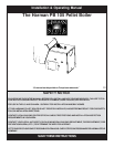


7
Design:
The first thing that needs to be done is deciding where and
how the boiler will be installed.
Things that need to be taken into consideration are the
intended use of the boiler for example, is the boiler going to
be used as your primary heating system or is it going to be
used as a secondary or backup heating system. If it is to be
used in conjunction with an existing oil or gas boiler system
will it be piped in parallel or in series? The answers to these
and other questions can be determined by talking to your
certified dealer or a qualified HVAC or plumbing contrac-
tor. This will insure that the boiler is installed and piped to
accommodate your needs and expectations.
Consideration must be given to the venting as well as
electrical and clearance requirements. (Clearances must be
maintained to combustibles and also for service)
After the boiler is set into place the venting can be done.
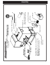
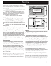
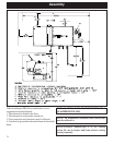
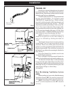
1. Install the control board cover as well as the access
cover located on the feeder cover.
2. Install the spring handles provided with the unit on
the ash door, firebox door and the heat exchanger cleanout
rod handles. (Fasten handles by turning them counterclock-
wise and pushing inward simultaneously).
3. Install 1/2” MPT boiler drain in the fitting as
shown.
Note: Use teflon pipe thread sealant or teflon
tape on ALL threads before connections are made.
4. Install 3/4” MPT pressure relief valve as shown.
5. Install the 1/2” MPT aquastat well in fitting as
shown, then place aquastat in the well and fasten with a zip
tie.
6. Install the 1/2” MPT temperature/pressure gauge in
fitting as shown.
7. Locate and install outside air temperature sensor.
Location of this sensor should be on the north side of the
home or building and out of direct sunlight. Use the cat
cable supplied with the boiler to attach sensor to the
terminals located on the hopper. (Place at the back side just
above and to the right of the main power connection box)
The wires can be connected to the sensor with the connec-
tors supplied. Wire nut or butt splice connectors could also
be used. The connections at the boiler can be done with the
two 1/4” female push on connectors supplied.
8. Fasten conduit to the ash base with the clamps
provided.
Assembly
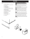
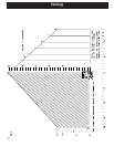
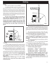
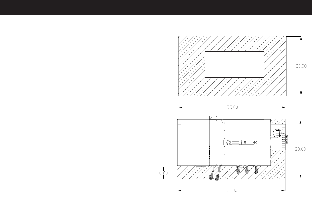
Floor Protection:
The striped area indicates the minimum required floor
protection area if the PB105 is going to be placed on a
combustible floor. It requires 30” X 55” of non combus-
tible floor protection as shown below. 6” of the floor
protection must be in front of the boiler as shown. Floor-
ing must be a minimum of 26 gauge sheet metal. Floor
protection must also be provided under any horizontal run
of vent pipe equal to the outside diameter of the venting
plus 2” to each side.
Example: 4” type “L” or “PL” vent pipe has an outside
diameter of 4-1/2” + 2” on each side equals a protected
floor area of 8-1/2” wide underneath the horizontal run.
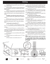
After assembly of the flue tunnel weldment, combustion
blower assembly with wiring and heat shield, the boiler can
now be installed.
Non-Combustible
Floor Protector
MINIMUM NON-COMBUSTIBLE FLOOR PROTECTION AREA
Make sure fans are not used in the fuel storage area, unless
they are installed so as not to create a negative pressures in
the room where the solid fuel burning appliance is located