


7
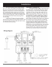
Wiring and Electrical
Followingthewiringdiagram,runallwires
totheirdesignatedconnections.Savethemain
powerforthelasthook-up,andleavethebreaker
intheoffposition.Thesensorwiresattachtothe
A350Controllerontheterminalsmarked“sen”
and“com”.Makesurethesensorissubmerged
fullyintothewellandsecuredwiththeset-screws.
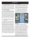
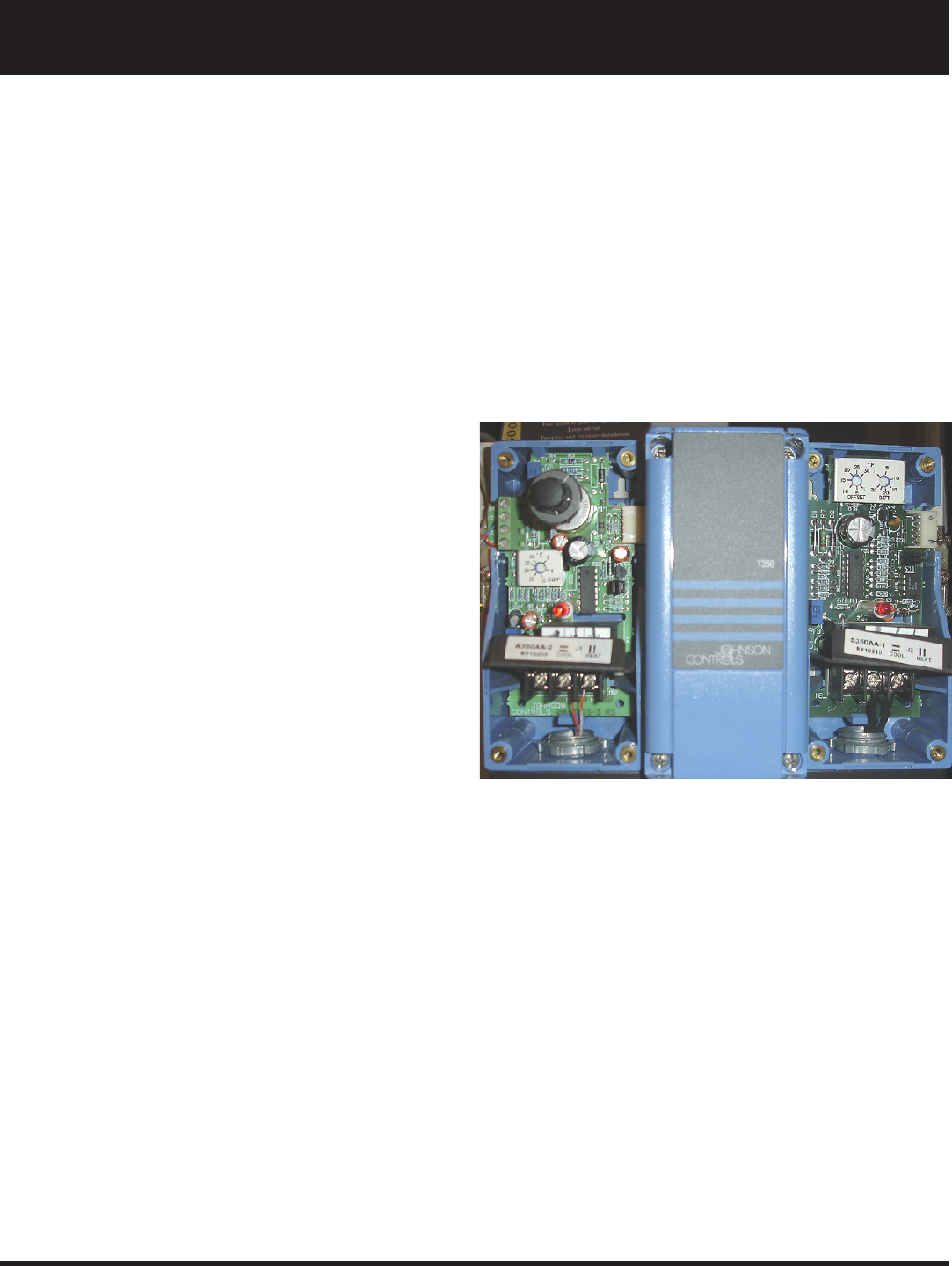
Setting The Aquastat
InsidetheA350control,youwillseea
squarejumper,andadifferentialdial.Besurethe
jumperisinthe“Heating”position.Thedifferen-
tialdialissettodeterminehowlow,belowthe
temperaturesetpoint,youwantthewatertem-
peraturetogobeforetheAutomaticDraftControl
opens.Agoodinitialsettingforthisdialis5°.Be
surethe120Vwiresareattachedtothecommon
andthenormallyopenterminals,andreplacethe
cover.Theexternaldialissetforthewatertem-
peratureyouwishtomaintain,agoodsettingis
180°.
Inside the Y350 control, ensure that your
wiresareconnectedtothe120VACterminals,
and replace the cover.
InsidetheS350control,whichisusedas
overheatprotection,you’llseetwodials;offset,
anddifferential.Thereisalsoajumperwhich,in
thiscase,getsplacedinthe“cooling”position.
Theoffsetdialsetsthenumberofdegreesabove
theA350setpointthatyouwanttheoverheat
dumptoactivate.Agoodsetpointwouldbe20°.
Thatwouldmeanthatifthewaterreaches200°,
usingtheA350setpointof180°,theS350would
close it’s contacts and energize the overheat
dumpzone.Thedifferentialdialsetsthepointthat
theoverheatdumpwouldstop.Withthedifferen-
tialsetat15°,usingthetemperaturesabove,the
circuitwouldre-open,stoppingtheoverheatdump
atawatertemperatureof185°.The120Vwiring
isattachedonthenormallyopenandthecommon
position.Thenormallyclosedpositionisnotused.
Re-install the covers onto the three Con-
trols.
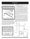
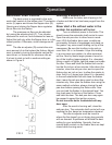
Optional Items
Thereisadomestichotwatercoilavailable
for your Trident Boiler. The coil installs in the front
oftheboiler,andallowsyourdomesticwaterto
beheatedbytheheatingsystemwater.Installthe
coilnow,byremovingtheroundplateandreplac-
ingitwiththecoilandit’sroundplate.Besureto
tightentheboltsevenly,toensureagoodseal.
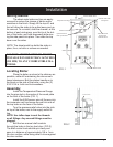
Ifelectricback-upisdesired,installnow.
Therewillbetwoadditionalcontrolboxestoadd
toyouraquastat,whichwillrequiretheuseof
alongerdinrail.Thetwoheatingelementswill
installintothefrontoftheboilerasshowninFig.1
FIG.4
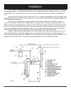
Venting
TheHarmanTridentBoilermustbein-
stalledintoachimneyapprovedforsolidfuel
burningappliances.IntheU.S.,theboilermustbe
connectedto;(1)aprefabricatedchimneycomply-
ingwiththerequirementsforTypeHTchimneysin
theStandardforChimneys,FactoryBuilt,Resi-
dential Type and Building Heating Appliances, UL
103.Or;(2)acodeapprovedmasonrychimney
withaueliner.InCanada,withprefabricated
chimneysystemstestedandlistedtotheHigh
TemperatureChimneyStandardULCS-629,or
withacodeapprovedmasonrychimney.The
minimumrecommendedheightforanychimney
is16ft.(4.8m)abovetheuecollar.Donotre-
duceuediameter.Nominalsizeueis8X8in.
or equivalent, up to 8 X 12 in. Codes also require
thatthechimneymustextendaminimumof
Installation