


7
XXV Pellet Stove
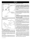
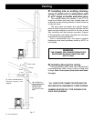
Place the stove on a non-combustible floor
protector that extends a minimum of 6 inches to
the front (152mm), 6 inches to the sides (152mm)
and 6"(152mm) to the rear, which is ush with the
rear of the hopper. Front and side oor protection
measurements are made from the rebox or window
opening. Floor protection must also be positioned
under horizontal ue pipe, extending 2" (51mm)
beyond each side of the pipe.
Per
ULC-S627-00, If installed on a combustible oor,
the need to provide a noncombustible oor protector
covering the area beneath the space heater and
extending at least 17.72" (450mm) on the ring side
and at least 7.87" (200mm) on the other sides.
The minimum oor protector material is 20 gauge sheet
metal. Other oor protector materials are ceramic tile, stone,
brick, etc.
Place the stove away from combustible walls at least as far
as shown in Figures 2 and 3.
Note that the clearances shown are minimum for safety but do
not leave much room for access when cleaning or servicing.
Please take this into account when placing the stove.
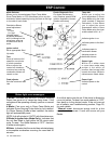
Connect the power cord to a 120 V.A.C. 60Hz grounded
receptacle. (A surge protector is recommended to protect the
circuit board.) Also be sure that the polarity of the outlet that
the stove is plugged into is correct.
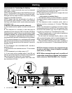
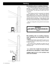
Prior to installing the ue pipe, connect a draft meter. Turn the
Feed Adjuster dial to "Test". Record the rst reading. Connect
ue pipe to stove and be sure all doors and windows in the
home are closed. Record the second draft reading_______.
If the second reading is more than .05" lower than the rst
reading, check for possible restrictions or the need for outside
air (see page 10). For more information on the draft test
procedure, refer to Page 17.
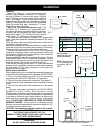
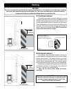
from back of
top ue vent
to wall
Fig. 5: Optional Top Vent Pipe Clearances
Fig. 2
from pipe to
wall
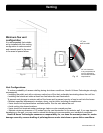
When installing this unit in a mobile home several requirements
must be followed
(Reference HUD Regulation #24CFR3280)
:
1. The unit must be bolted to the oor. This can be done by
using clips (part # 2-00-677110B) and 1/4" lag screws.
2. The unit must be connected to outside air. See page 10.
3. Floor protection and clearances must be followed as shown
above.
4. Unit must be grounded to the metal frame of the mobile
home.
5. Chimney must meet requirements of CAN/ULC-S629,
Standard for 650°C Factory Built Chimneys. Follow
Manufacturer's guidelines concerning height and clearances
to combustibles. Use the same manufacturer's components
to provide an effective vapor barrier where the chimney or
other component penetrates to the the exterior of the mobile
home.
The top section of chimney and the
chimney cap must be removable to a maximum height of 13.5'
for transport of the mobile home.
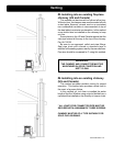
Fig. 3
US
Canada
Sides
Rear
6" 200mm
0" 200mm
Front
6" 450mm
Measurement
"K" is measured from
the glass in the US
ONLY
Floor protector