


Page 4SKU 39860
For technical questions, please call 1-800-444-3353.
Assembly
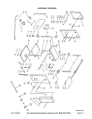
Your Planer requires only limited assembly as indicated below; otherwise it is fully assembled. To assist you
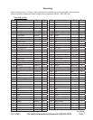
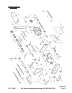
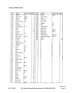
with assembly and operation please refer to the Assembly Diagram and Parts List located on pages 8,9,10
and 11. Lay out all parts onto a clear section of your workbench prior to assembly.
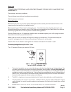
The Planer has four (4) legs so that it can be mounted to a table or a work bench. Each of these legs/1.
angles (4) should be attached at one side (bottom corners) to the Planer and then 2 of the 5/16” bolts
should be bolted onto the workbench with a washer between the Bolt and the workbench or table.
To put the Handle (part #150) onto the Planer, insert it into the hole on the right front side of the Planer 2.
and press it into place. WARNING! Check blade setting and tightness before initial use.
Operation
When operating your Planer, refer to the Parts List and Assembly Diagram on the last pages of this manual.
Never force the tool or attachment to do the work of a larger industrial tool. It is designed to do the job better
and more safely at the rate for which it was intended. Plane only wood boards.
After planing approximately 50 feet of material, stop machine and check Cutterhead Jib screws and blades for
tightness.
Do not force feed your work through the machine. Allow the Planer to feed at the designated rate of feed.
Step 1) Use the Height Adjusting Handle (part #150) to set the blade height. Set the height according
to the indicating scale on the Planer beneath the Handle.
Note: This Planer is specifically designed for the planing of lumber. Before planing any lumber,
check for any foreign materials such as nails, screws, or hard impurities in the wood. Also
check for loose knots in the wood. If not cleaned off these may cause damage to the blade or
machine. Never make a Planer cut deeper than 1/8”.
When feeding your lumber, use a Push Block to feed the lumber, rather than using your
hands. The Push Block must be thinner than 3 inches.
Step 2) The ON and OFF switch is located on the front of the Planer. Press the GREEN button to
START the Planer, and RED button to turn the Planer OFF.
Step 3) The planing depth of the planer is controlled by turning the Handle and setting the depth of
the Planer by the Ruler. The settings on the Ruler run from 0” to 6”.
Step 4) Feed lumber through Planer. After each planing, you can use the Roller Bars on top of the
planer to roll the workpiece back to the Feed position, rather than carrying it back and forth.
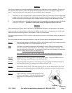
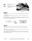
Checking the Knife Gauge for Proper Height
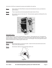
Step 1) Loosen all screws. Place the knife gauge as shown
in Figure 1 and Figure 2. Use the wrench key and the
turn screw (D) until the blade (C) touches the knife
gauge.
Figure 1
REV 06a; 10h