


4
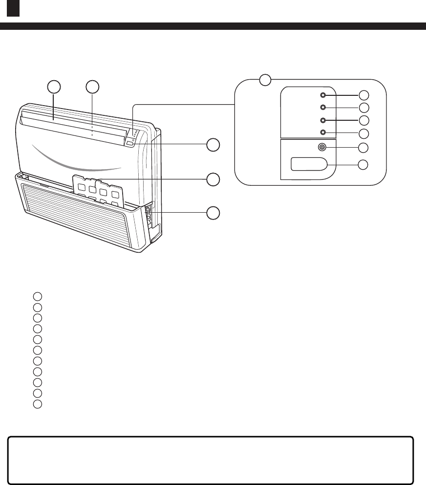
Name of Parts
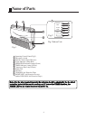
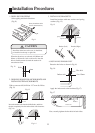
Fig.1 Indoor Unit
1
4
6
7
3
Fig.2
POWER
OPER
TIMER
COMP
EMER
2
3
9
8
Fig.1
1110
Note : For the wired control type unit, the unit state should be checked by the the wired
controller, instead of the remote receiver; and if you set the TIMER function, the
TIMER LED on the remote receiver will not be on.
1 Operating Control Panel (Fig.2)
2 Emergency switch
3 Remote Control Signal Receiver
4 Power Indicator Lamp (Red)
5 OPERATION Indicator Lamp (Green)
6 TIMER Indicator Lamp (Yellow)
7 Compressor Run Lamp (Green)
8 Intake Grill
9 Air Filter
10
UP/DOWN Air Direction Flaps
11
RIGHT/LEFT Air Direction Louvers
(behind UP/DOWN Air Direction Flaps)
5