


14
Installation Procedures
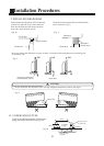
ELECTRICAL REQUIREMENT
Electric wire size and fuse capacity:
Table 5
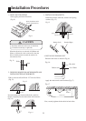
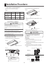
ELECTRICAL WIRING
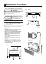
1. INDOOR UNIT SIDE
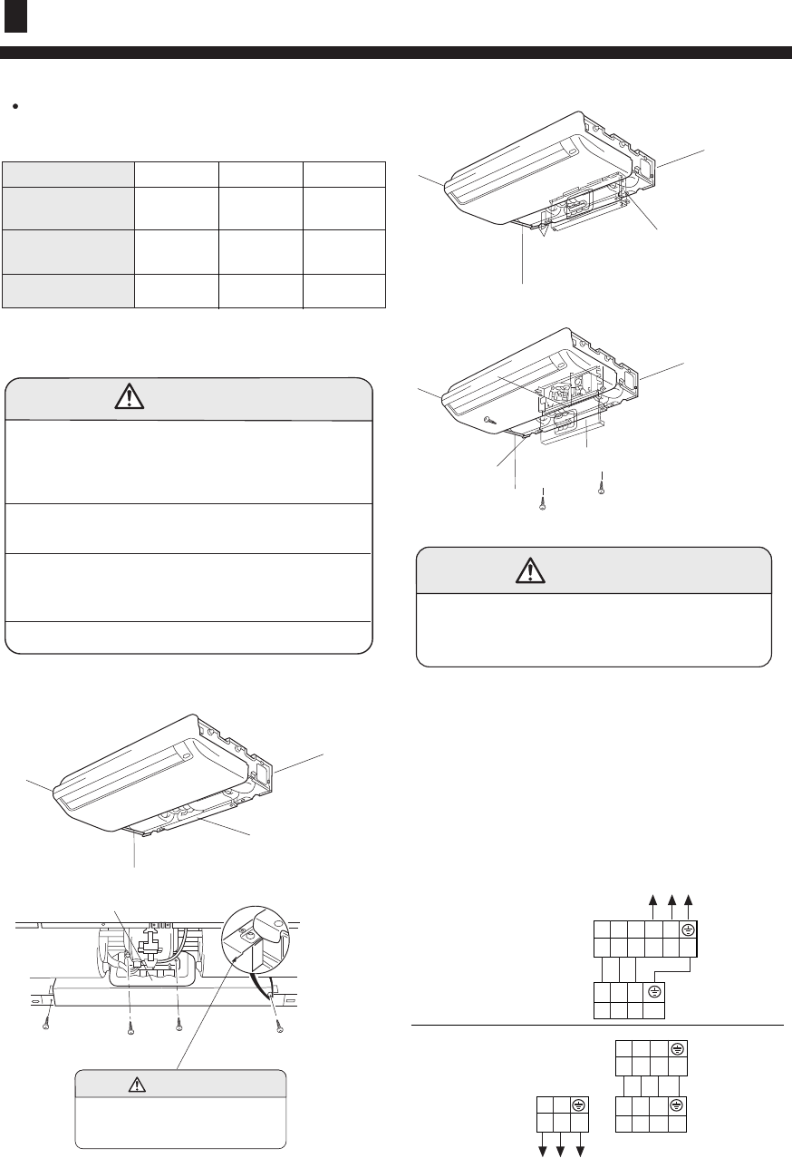
(1) Remove the electric component box.
(2) Pull out the electric component box.
Fig.28
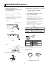
(3) Remove the electric component box cover.
Fig. 29
Base
Electric component box cover
Remove the three tapping screws.
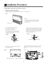
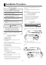
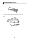
(1) Remove the cord clamp.
(2) Process the end of the connection cords to the
dimensions shown in Fig.34.
(3) Connect the end of the connection cord fully into the
terminal block.
(4) Wiring
(4) Fasten the connection cord with a cord clamp.
(5) Fasten the end of the connection cord with the
screw.
Electric component box
CAUTION
Be careful not to pinch the lead wires
between the electric component box
and base.
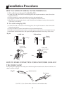
CAUTION
(1) Match the terminal block numbers and connection
cord colors with those of the outdoor unit.
Erroneous wiring may cause burning of the electric
parts.
(2) Connect the connection cords firmly to the terminal
block. Imperfect installation may cause a fire.
(3) Always fasten the outside covering of the connection
cord with the cord clamp.(If the insulator is chafed,
electric leakage may occur.)
(4) Always connect the ground wire.
Power supply
cord (mm
2
)
Fuse capacity(A)
2.5
30
Connection cord
(mm
2
)
Type
0.75
Fig. 26
Electric component box
Fig. 27
Electric component box
Remove the four tapping
screws.
CAUTION
Do not remove the screws. If the screws
are removed, the electric component
box will fall.
0.75 0.75
2.5 4.0
30 40
For series 142 For series 182 For series 242
Power supply: 1PH, 220-230V~, 50Hz
L N
1 2 3
1 2 3
OUTDOOR UNIT
TERMINAL BLOCK
INDOOR UNIT
TERMINAL BLOCK
Power supply: 1PH, 220-230V~, 50Hz
1 2 3 N L
1 2 3
INDOOR UNIT
TERMINAL BLOCK
OUTDOOR UNIT
TERMINAL BLOCK