


4
4
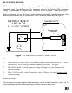
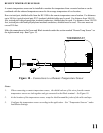
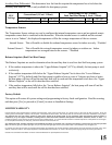
TYPICAL WIRING DIAGRAMS
CAUTION:
Do not short gas valve, fan, heat relay, or cool relay...even momentarily.
Do not attempt to hook up to live circuits. An accidental connection to a component on the thermostat circuit
board could cause damage to the thermostat.
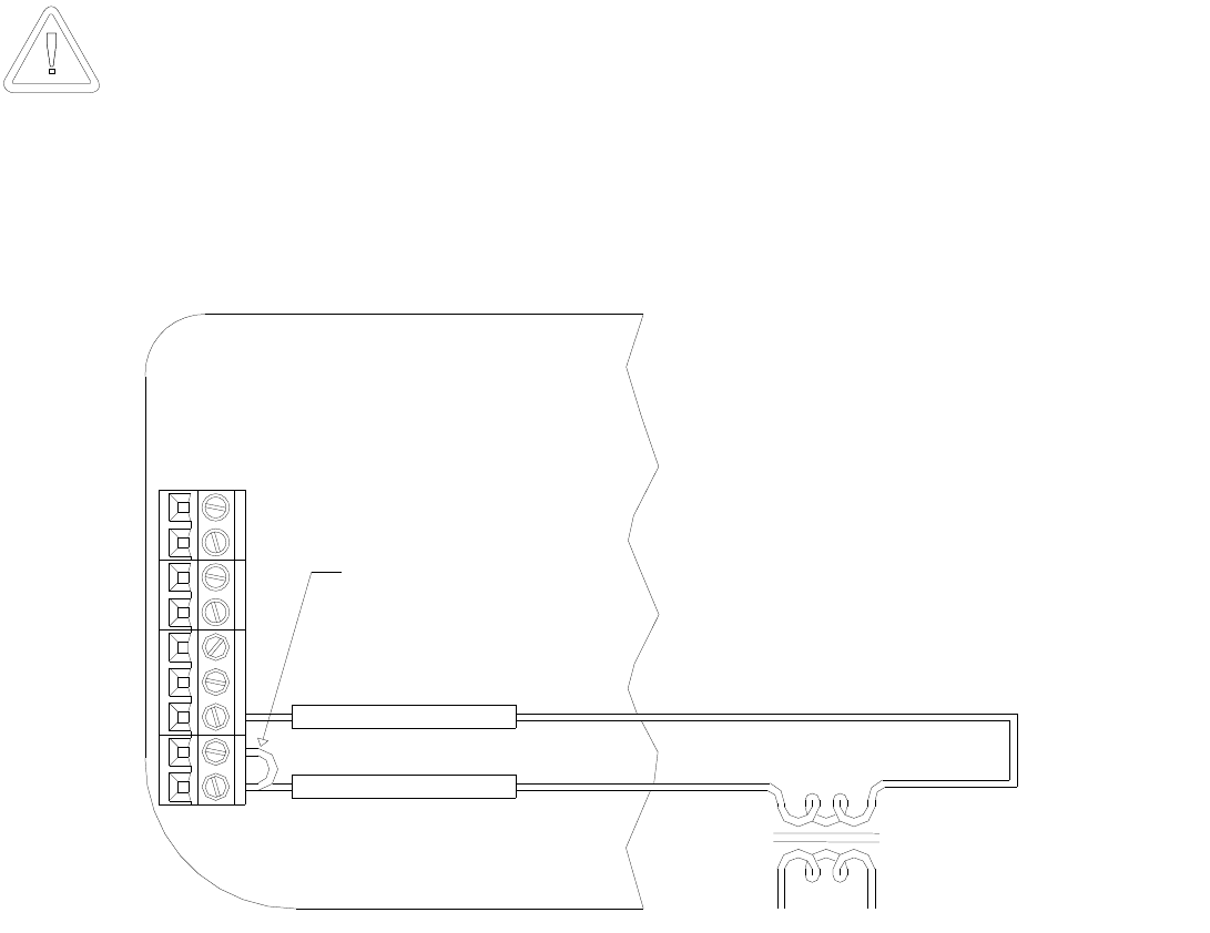
24VAC "HOT"
24VAC Common
24VAC
CONTROL
TRANSMFOMER
THERMOSTAT
UP
1
3
(C)
(RC)
JUMPER
2
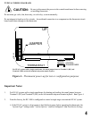
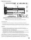
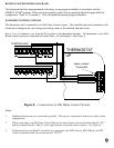
For HVAC systems with a single transformer, the metal jumper between Terminal 1 (RC) and
Terminal 2 (RH) on the left terminal strip must remain in place.
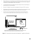
Figure 4 – Thermostat power-up for test or configuration purposes
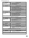
Important Notes:
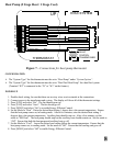
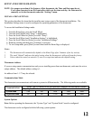
1. For HVAC systems with a single transformer for heating and cooling, the metal jumper between
Terminal 1 (RC) and Terminal 2 (RH) on the left terminal strip must remain in place – See Figure 4.
2. From the factory, the RC-1000 is configured to control a single stage conventional HVAC system.
¾ If the HVAC system is a heat pump or dual fuel heat pump, before operating the thermostat, the
“System Type” settings under “System Options” must be configured – See Installation Settings.
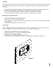
Be sure to disconnect the power to the control transformer before removing
or installing thermostat.