


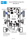
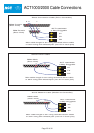

LED2
LED1
DOOR I/O
SERIAL NETWORK
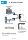
ENTRY/EXIT READER
GENERAL I/O
RELAY
TAMPER
MAINS
+12V
0V
N/C C
AUX RLY
N/ON/C C N/O
SENSE
CLOCK
DATA
+5V
0V
RED
GREEN
5A 250VAC
5A 30VDC
5A 250VAC
5A 30VDC
PUSH BUTTON
DOOR CONTACT
AUX
0V
OP2
OP3
1 2 3 4 5 6 7 8
W P 2 Address
On
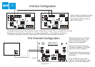
Interlock Configuration
LED2
LED1
DOOR I/O
SERIAL NETWORK
ENTRY/EXIT READER
GENERAL I/O
RELAY
TAMPER
MAINS
+12V
0V
N/C C
AUX RLY
N/ON/C C N/O
SENSE
CLOCK
DATA
+5V
0V
RED
GREEN
5A 250VAC
5A 30VDC
5A 250VAC
5A 30VDC
PUSH BUTTON
DOOR CONTACT
AUX
0V
OP2
OP3
1 2 3 4 5 6 7 8
W P 2 Address
On
Fire Override Configuration
1A 250VAC
1A 30VDC
0 1 2 3 4 5 6 7 8 9
BATCH:
PRODUCT:
SERIAL NUMBER:
98XX-1
ACT2000 REV2.1
00XXXX
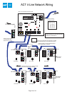
0V
DOOR
CONTACT
PUSH
BUTTON
AUX
INPUT
RELAY 1
N/C N/O
C
OP2
OP3
5A 250VAC
5A 30VDC
1A 250VAC
1A 30VDC
5A 250VAC
5A 30VDC
OUTPUTS 1 INPUTS
0V
DOOR
CONTACT
PUSH
BUTTON
AUX
INPUT
OP2
OP3
OUTPUTS 2 INPUTS
TAMPER
MAINS
PRESENT
+12V DC
AUX RLY 1
N/C N/O
C
RELAY 2
N/C N/O
C
AUX RLY 2
N/C N/O
C
- DC
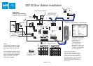
FIRE
N/C N/O
C
FIRE ALARM PANEL
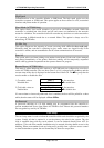
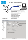
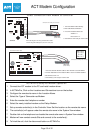
While the 0V signal is maintained
at the AUX input on Door 1, the
doors in the Fire Doors group
maintain normal operation.
When the 0V signal is removed,
the doors are opened, and remain
open until, the 0V is restored.
To set the Fire Doors group, go to
Installer Menu > System Settings >
Fire Doors.
From ACTWinPro, go to View >
Options > Doors and select a door
group for the Fire Override doors.
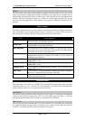
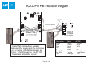
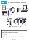
The diagram above shows how to interlock 2 doors. When Door 3 is open, Door 4 is locked and vice versa.
Remember to set Interlock for each door to Yes (See Installer Menu > Door Settings > Operation).
To Interlock more doors, simply continue linking OP3 and AUX for each new door, as above.
Door 3
Door 4
When Interlock is enabled on a door,
the door is locked when the AUX
input is active. When the door is
open, OP3 is active.
Page 26 of 32
ACT2000
Technical Manuals Online! - http://www.tech-man.com