


35
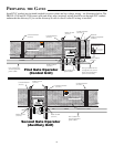
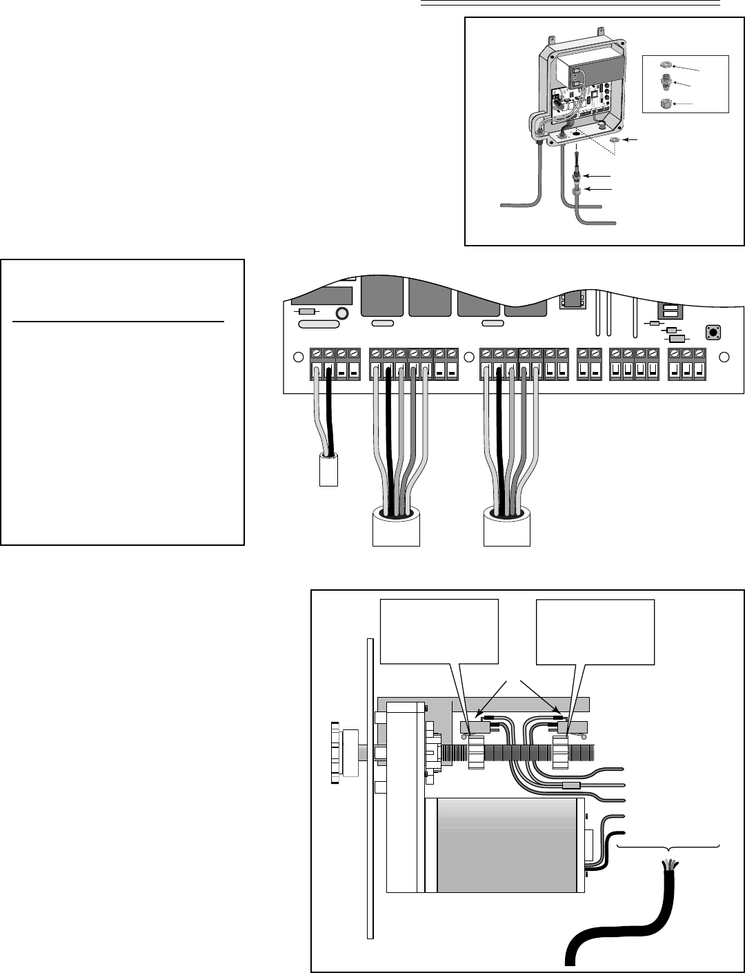
Limit Nut A
Open position stop –
if gate opens right to left.
Closed position stop –
if gate opens left to right.
Limit Nut B
Closed position stop –
if gate opens right to left.
Open position stop –
if gate opens left to right.
ORANGE (N/O contact)
BLUE (N/O contact)
GREEN (common)
BLACK to Motor RED
RED to Motor BLACK
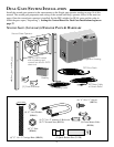
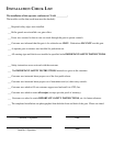
Second Operator
Power Cable
Limit Switches
Motor
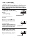
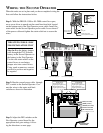
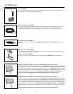
WIRING THE SECOND OPERATOR
Step 1: With the PRO SL-1000 or SL-2000 control box open,
use a screw driver to punch out the round knockout hole located
on the bottom next to the First Operator power cable. Install the
strain relief for the Second Operator power cable. Leave about 6”
of the power cable and tighten the strain relief nut to secure the
wires.
Step 2: Run the second power cable through
PVC conduit to the Second Operator. Con-
nect the wires to the motor and limit
switches as shown in illustration
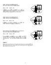
Step 3: Adjust the DIP switches on the
First Operator control board for the
appropriate dual gate settings, follow-
ing the directions on next page.
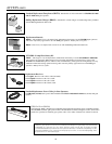
When the units are set in place and you have completed wiring the
first unit follow the instructions below.
ON
SECOND OPERATORFIRST OPERATORPOWER IN ALARM ACCESSORY RCVR
SEQ1
SEQ2
LEARN
18VAC SOLAR
~~– +
RED
BLK
ORG
BLU
GRN
CLS EDG
OPN EDG
RED
BLK
BLU
ORG
ORG
BLU
WHT
GRN
GRN
CLS EDG
OPN EDG
R B G
Power Cable
from First Operator
Power Cable
from Second Operator
Low Voltage Wire
from AC Transformer
RED
BLACK
ORANGE
BLUE
GREEN
RED
BLACK
ORANGE
BLUE
GREEN
RED
BLACK
ORANGE
BLUE
GREEN
RED
BLACK
ORANGE
BLUE
GREEN
First Operator Power Cable
Second Operator Power Cable
R
E
D
B
L
K
O
R
G
B
L
U
G
R
N
C
L
S
E
D
G
O
P
N
E
D
G
R
E
D
G
R
N
O
R
G
B
L
U
W
H
T
B
L
K
O
R
G
B
L
U
G
R
N
C
L
S
E
D
G
O
P
N
E
D
G
LE
AR
N
AUTO
CL
OSE
INERTIA
STAT
US
STATUS
BATT
BATT
+
–
OBSTR.
SE
NS.
R
C
V
R
R
G
B
A
LA
R
M
S
E
C
O
N
D
O
P
E
R
A
T
O
R
F
IR
S
T
O
P
E
R
A
T
O
R
P
OWER IN
1
8
V
A
C
S
O
L
A
R
~
~
–
+
A
C
C
E
SS
O
R
Y
P
W
R
.
S
W
.
P
WR. SW.
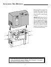
Lock Nut
Hub
Sealing Nut
Sealing Nut
Hub
Lock Nut
Strain Relief
Wire From Second
Operator Battery
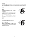
THIS STEP IS FOR SL-2000/
2200 INSTALLATION ONLY
Step 1a: Run the battery jumper
wire through the PVC from the
battery in the Second Operator to
the battery in the First Operator.
Use the side strain reliefs on the
control boxes to run battery
jumper wire into control boxes.
Using spade connectors, connect
positive to positive and negative
to negative.