


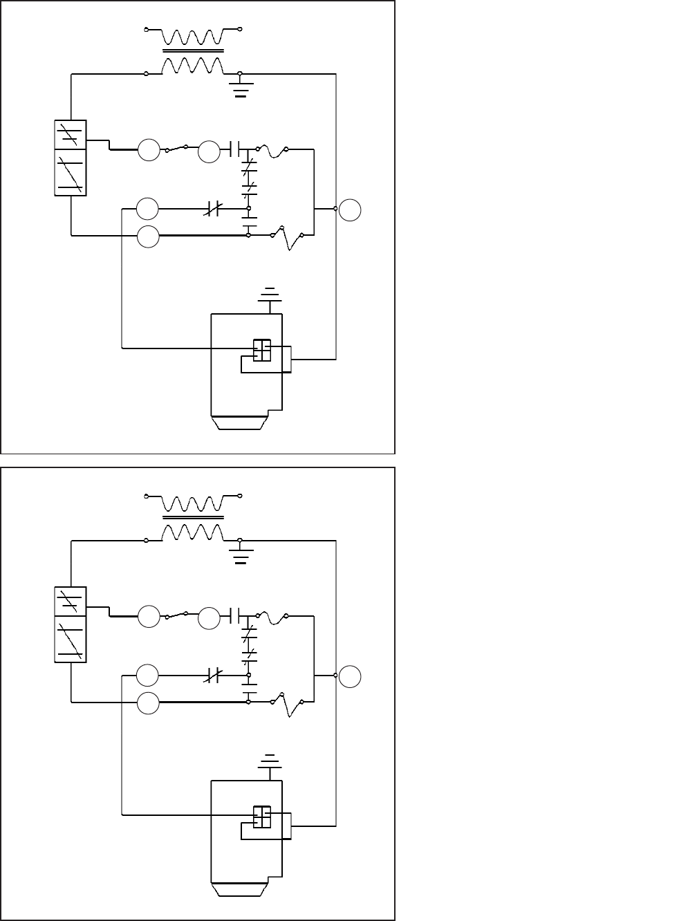
20 VAC
24 VAC
E.C.O.
TH.
R1 (N.C.)
FUSE
R2 (N.O.)
SS2 (N.O.)
E.S.(N.O.)
VENT DAMPER
VALVE
GND.
2
M
3
4
1
20 VAC
24 VAC
E.C.O.
TH.
R1 (N.C.)
FUSE
R2 (N.O.)
SS2 (N.O.)
E.S.(N.O.)
VENT DAMPER
VALVE
GND.
2
M
3
4
1
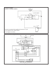
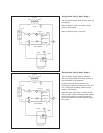
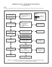
On Appliance Call for Heat - Stage 1
The thermostat contacts close and they relay coil
is energized.
Relay contacts R1 (N.C.) now open, and the
motor is de-energized.
Relay contacts R2 (N.O.) now close.
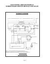
On Appliance Call for Heat - Stage 2
The flue damper spring begins to operate to
return the damper blade to the open position to
permit operation of the appliance.
During this damper blade movement, the
mechanically operated switches (SS1, SS2, and
E.S.) change their operating positions, which
results in the following:
When the switch SS2 opens, it causes the SS1
switch to close. When the damper blade reaches
the full open position, the switch contacts ES
close and the electrical circuit energizes the igni-
tion system.
Page 8