FLUE DAMPER
Flue Damper Installation
For Models equipped with a flue damper, the following instructions
must be followed. It is recommended to leave a minimum 24”
clearance from the actuator side of the flue damper for service
access.
S
tep 1:
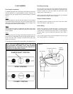
Place flue damper on top pan into flue collector. The rail support
must be screwed to the top pan. The three pre-drilled holes on the
casing top must align with the three holes on the rail support. The
rail support must fit flush with the casing top.
S
tep 2:
Install the draft hood which is supplied with the heater in the carton
to the heater top. Fasten the draft hood with the four sheet metal
screws supplied.
S
tep 3:
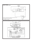
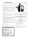
Remove junction box cover plugs. Remove flue damper cover. The
wiring harness provided plugs into the four plug female molex con-
nector (use strain relief connector provided). Molex plugs mate
together one way only.
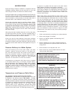
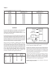
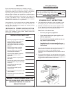
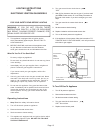
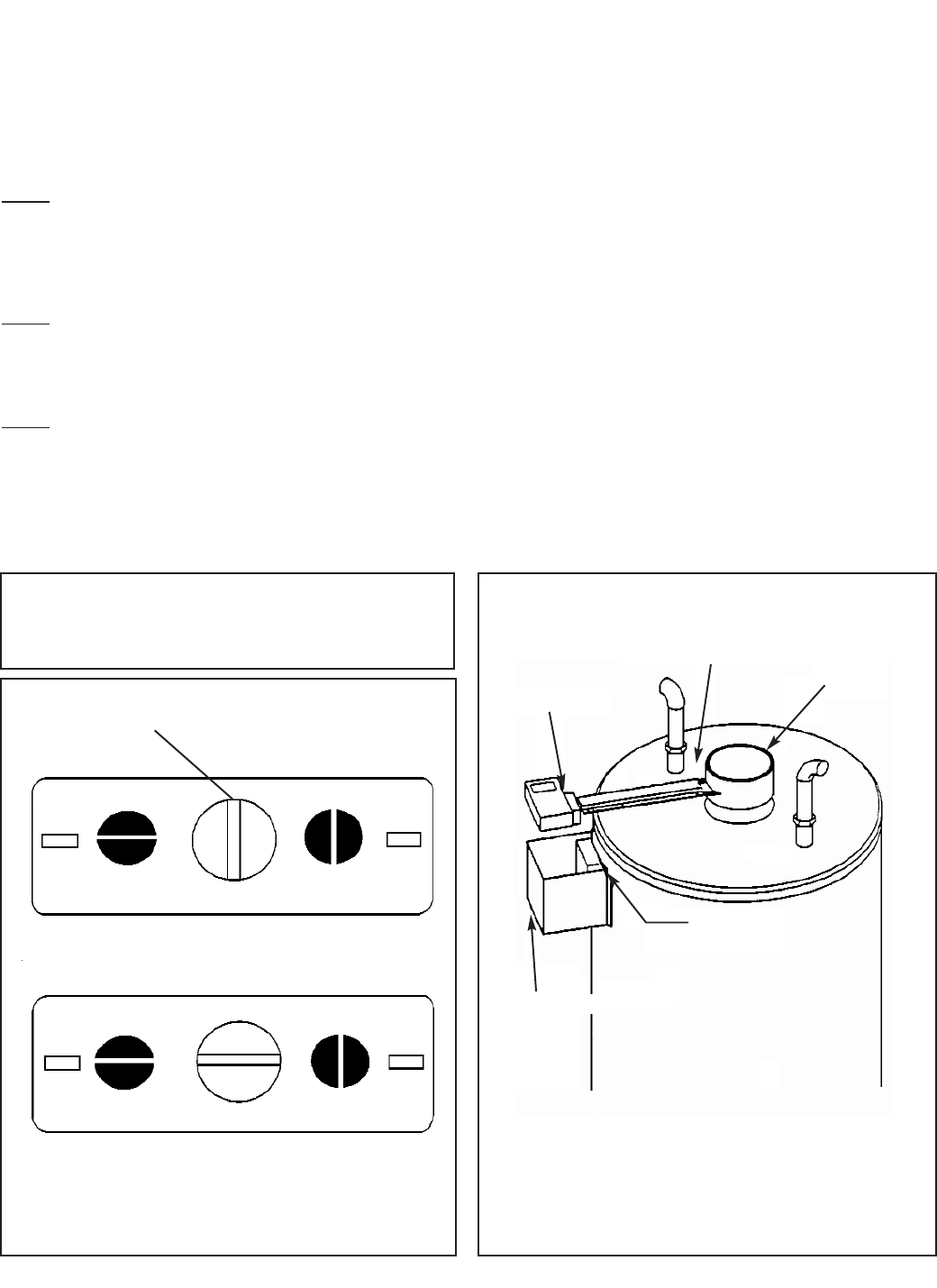
To manually set the damper in the open position, see diagram below.
Flue Damper Venting
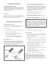
The vent pipe (flue pipe) must be installed without restriction
or reduction in size. Slope the horizontal run upwards to the
chimney at least 1/4” per foot. Fasten all joints with sheet
metal screws. (See Figure 4)
Venting must be inspected every three months for blockage
and problems due to age of the vent piping.
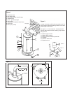
Damper Position Indicator
The damper position indicator can be found on the flue collar
of the flue damper. (See Figure 4).
Heater Wiring
Follow local codes for all electrical work. To reduce risk of
shock or possible electrocution, the heater must be electrical-
ly grounded in accordance with local codes or, in the absence
of local codes, with the National Electrical Code, ANSI /
NFPA 70.
If any of the original wiring must be replaced use only type
105
o
C thermoplastic or equivalent.
NOTE: THE FLUE DAMPER MUST BE IN THE OPEN
POSITION WHEN APPLIANCE, PILOT AND OR MAIN
BURNERS ARE ON. THIS SHOULD BE CHECKED BY
THE INSTALLER BEFORE LEAVING.
DAMPER SHAFT POSITION
“OPEN” POSITION
“CLOSED” POSITION
CLOSED
OPEN
CLOSED
OPEN
Figure 4
COLD
HOT
MOUNTING SCREWS (4)
DAMPER
POSITION
INDICATOR
JUNCTION BOX
JUNCTION BOX COVER
VENT DAMPER
Page 6


