


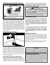
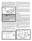

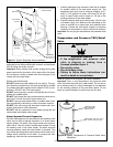
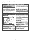
The 60 gallon heater is equipped with a Heat Reflector
Shield (see Figure 2). This Shield reflects heat from the
High-input heaters to prevent damage to combustible floors.
The Shield is held in place by three (3) tabs that rest on the
inside of the legs of the water heater. Ensure the Shield is
positioned horizontally (parallel to the bottom of the heater)
and in the designated position of 38mm (1.5 in.) below the
flame-arrester.
The water heater shall be located in an area not subject to
freezing temperatures. Water heaters located in uncondi-
tioned spaces (e.g., attics, basements, etc.) may require
insulation of the water and drain piping to protect against
freezing. Proper ventilation needs to be provided for water
heaters installed in unconditioned spaces (e.g., attics, base-
ments, etc.) in order to avoid an event where air tempera-
ture exceeds 42°C (108°F). The drain and controls must be
easily accessible for operation and service. Maintain proper
clearances as specified on the data plate.
Ensure that the water heater is level. This heater may be
installed in a closet or alcove and is certified for operation
on a combustible floor.
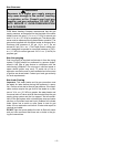
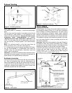
Do not locate the water heater near an air-moving device.
The operation of air-moving devices such as exhaust fans,
ventilation systems, clothes dryers, fireplaces, etc., can
affect the proper operation of the water heater. Special
attention must be given to conditions these devices may
create. Flow reversal of flue gases may cause an increase
of carbon monoxide inside of the dwelling, as shown in
Figure 7.
If the water heater is located in an area that is subject to an
excessive amount of lint, dirt or oil, it may be necessary to
clean the flame arrester periodically (see “Maintenance”
section).
Important: It is always recommended that a suitable drain
pan be installed under the water heater to protect the area
from water damage resulting from normal condensation, a
leaking tank or piping connections. Refer to Figure 1. Under
no circumstances is the manufacturer to be held responsi-
ble for any water damage in connection with this water
heater.
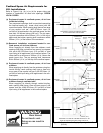
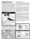
Gas Supply
Install the gas piping as shown in Figure 4. Use only new
pipe and fittings with clean-cut threads. Sealing compounds
used on the pipe threads shall be approved for use with nat-
ural and propane gas.
Use gas piping of adequate sizing to ensure gas input. Gas
piping material must be approved for use with natural gas
and propane fuels. All piping must comply with all local
codes or, in the absence of such codes, with the latest edi-
tion of “Natural Gas and Propane Installation Code”
CAN/CSA-B149.1 in Canada, “National Fuel Gas Code”
ANSI Z223.1 (NFPA 54) in the U.S.A. The final connection
to the water heater is made using 1/2” NPT.
Before connecting to the gas service, check that a properly
sized gas meter and regulator are available to service the
water heater. If other appliances are using the same meter
and regulator, ensure that the capacity of the meter and reg-
ulator matches that of the combined input of all appliances
connected to it.
DO NOT tamper with the gas control/thermostat, igniter,
thermocouple, or temperature and pressure relief valve.
Tampering voids all warranties. Only a qualified service
technician should service these components.
WARNING
Do not install directly on carpet. Instead, place the
water heater on a metal or wood panel extending a
minimum of 75mm (3 in.) from all sides. In alcoves or
closets, cover the carpet completely. Ensure this
panel is capable of supporting the weight of this
heater when filled with water.
FAILURE TO PROPERLY INSTALL THIS HEATER MAY
RESULT IN A FIRE HAZARD.
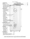
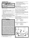
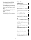
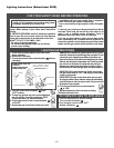
Figure 3 Minimum Clearance Locations
AIR INTAKE
VENT
FRONT 600mm
(24 in.) MIN.
FOR SERVICE
BACK 25mm (1 in.)
SIDES
25mm
(1 in.)
SIDES AND
BACK 25mm
(1 in.)
TOP TO CEILING
200mm (8 in.)
Figure 2 Heat Shield Installation (60 gallon only)
HEAT SHIELD
FLAME
ARRESTER
DRAIN
VALVE
LEG
BOTTOM
PAN
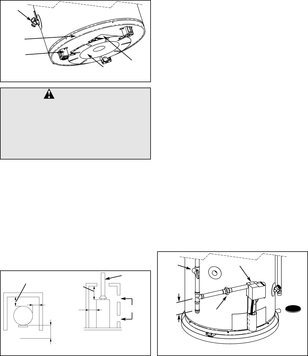
Figure 4 Recommended Gas Piping
GROUND-
JOINT UNION
MANUAL
GAS
SHUT-OFF
GAS CONTROL/THERMOSTAT
75mm (3 in.)
– 7 –