


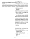
Note: Visually inspect the flame arrester by placing a mirror
underneath the water heater. A flashlight can be used to illu-
minate the slots in the flame arrester if necessary. Routine
cleaning of the flame arrester is recommended if inspection
shows accumulation of debris on the flame arrester. See
section titled “External Cleaning of the Flame-arrester” for
cleaning instructions.
Important: Verify proper operation after servicing this water
heater. If you are unsure of this inspection procedure or the
proper operation of the water heater and its special safety
features, enlist the services of a qualified service technician.
External Cleaning of the
Flame-arrester
Important: It is recommended that the flame arrester be
visually inspected periodically for accumulation of dust, lint
and other debris, especially if the heater is installed in areas
having a high dust and/or lint content. Any such accumula-
tion should be cleaned as outlined below.
1. Use a vacuum cleaner to remove all loose debris in the
flame arrester.
2. If necessary, a soft bristle brush can be used to dis-
lodge any remaining debris.
3. Repeat step 1 as necessary to completion.
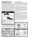
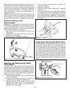
Resetting and Replacing the Safety
(TCO) Switch
The water heater safety system includes a door-mount,
manual resettable, safety switch which is designed to dis-
able the gas control/thermostat in the event of excessive
combustion chamber temperatures. The excessive combus-
tion chamber temperatures may be generated by accumu-
lation of lint and dust on the flame-arrester (located under-
neath the combustion chamber),
1. Follow first the procedure outlined in "External Cleaning
of the Flame-arrester".
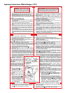
2. Remove the outer door and locate the TCO switch on
the right side of the combustion chamber door.
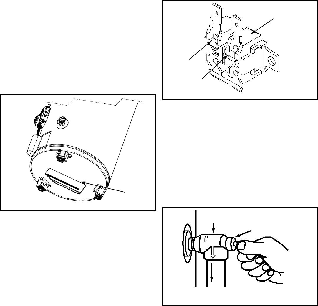
3. Manually press the contact located on the front-right
side of the TCO switch (Figure 17) until a click sound is
generated. Do not use a metal tool or a screwdriver to
press the TCO switch contact.
4. Verify if the quick connects are firmly inserted in the
TCO switch contacts.
5. Replace the outer door.
6. Restart the water heater following the “Operating
Instructions”.
7. If the pilot burner does not stay lit after several attempts
it is possible that the TCO embedded in the safety
switch opened due to a flammable vapor incident or the
TCO switch was severely damaged. Do not attempt to
further operate the water heater. Call a qualified service
technician.
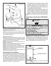
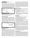
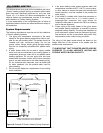
Temperature and Pressure Relief Valve
Manually operate the temperature and pressure relief valve
at least once a year to make sure it is working properly. To
prevent water damage, the valve must be properly connect-
ed to a discharge line which terminates at an adequate
drain. Standing clear of the outlet (discharged water may be
hot), slowly lift and release the lever handle on the temper-
ature and pressure relief valve (see Figure 18) to allow the
valve to operate freely and return to its closed position. If the
valve fails to completely reset and continues to release
water, immediately shut off the manual gas shut-off valve
and the cold water inlet and call a qualified service techni-
cian.
Figure 17 TCO Switch
TCO
RESET
CONTACT
THERMAL
LINK
Figure 18 T&P Relief Valve Test
TEMPERATURE AND
PRESSURE RELIEF VALVE
MANUAL RELIEF VALVE
DISCHARGE LINE TO DRAIN
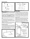
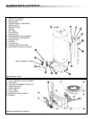
Figure 16 Flame Arrester (External View)
FLAME
ARRESTER
– 20 –