


III) INSTALLATION
Unpacking the Water Heater
Important: Do not remove any permanent instructions,
labels or the rating plate from the outside of the water heater
or on the inside of panels.
1. Move the water heater to the location of installation
before removing the exterior packaging.
2. Remove exterior packaging and place installation com-
ponents aside.
3. Inspect all parts for damage prior to installation and
start-up.
4. Completely read and understand all instructions before
attempting to assemble and install this product.
If you observe damage to the water heater or any of its com-
ponents, DO NOT ASSEMBLE OR INSTALL IT OR MAKE
ANY ATTEMPT TO FIX THE DAMAGED PART(S). Contact
the place of purchase for further instructions.
5. After installation, dispose of packaging material in the
proper manner.
Location Requirements
Note: Before installing this water heater, consideration and
planning must be given to the following details:
•
Location and Clearances.
•
Access for gas supply; See “Gas Supply”.
•
How and where to obtain combustion and ventilation air
supply; See “Air Requirements”.
•
Routing and support of the vent piping.
•
Position of water supply and placement of water piping
for hot and cold water; See “Water Supply”.
•
Floor drain and service.
In Earthquake Zones
Note: The water heater must be braced, anchored, or
strapped to avoid moving during an earthquake. Contact
local utilities for code requirements in your area.
Note: REVIEW SAFETY WARNINGS FOUND IN THE
FRONT OF THIS MANUAL BEFORE PROCEEDING
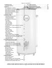
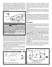
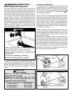
Clearances and Accessibility
Specific clearance locations are shown in Figure 3. A mini-
mum of 600mm (24 in.) of front clearance shall be provided
for inspection and service. We recommend that 0.9m (36
in.) above be maintained for serviceability.
Locate the water heater such that all controls are easily
accessible.
Clearance to combustibles varies by model. Refer to rating
plate to confirm clearances.
Heaters with a volume of 19 gallons through 50 gallons and
60 gallon (standard input) must have the following minimum
clearances to combustibles:
Front 102mm (4 in.)
Sides and Rear 25mm (1 in.)
Top 203mm (8 in.)
Flue 152mm (6 in.)
JW6058 and G6058 (high input) series heaters must have
the following minimum clearances to combustibles:
Front 127mm (5 in.)
Sides and Rear 25mm (1 in.)
Top 203mm (8 in.)
Flue 152mm (6 in.)
WARNING
Excessive Weight Hazard
Use two or more people to move and install
water heater. Failure to do so can result in
back or other injury.
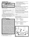
IMPORTANT:
This water heater must be installed strictly in accordance
with the instructions enclosed, and local electrical, fuel
and building codes. It is possible that connections to the
water heater, or the water heater itself, may develop
leaks. IT IS THEREFORE IMPERATIVE that the water
heater be installed so that any leakage of the tank or relat-
ed water piping is directed to an adequate drain in such a
manner that it cannot damage the building, furniture, floor
covering, adjacent areas, lower floors of the structure or
other property subject to water damage. This is particular-
ly important if the water heater is installed in a multi-story
building, on finished flooring or carpeted surfaces. GSW
WILL NOT ASSUME ANY LIABILITY for damage caused
by water leaking from the water heater, pressure relief
valve, or related fittings. Select a location as centralized
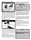
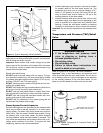
within the piping system as possible. In any location
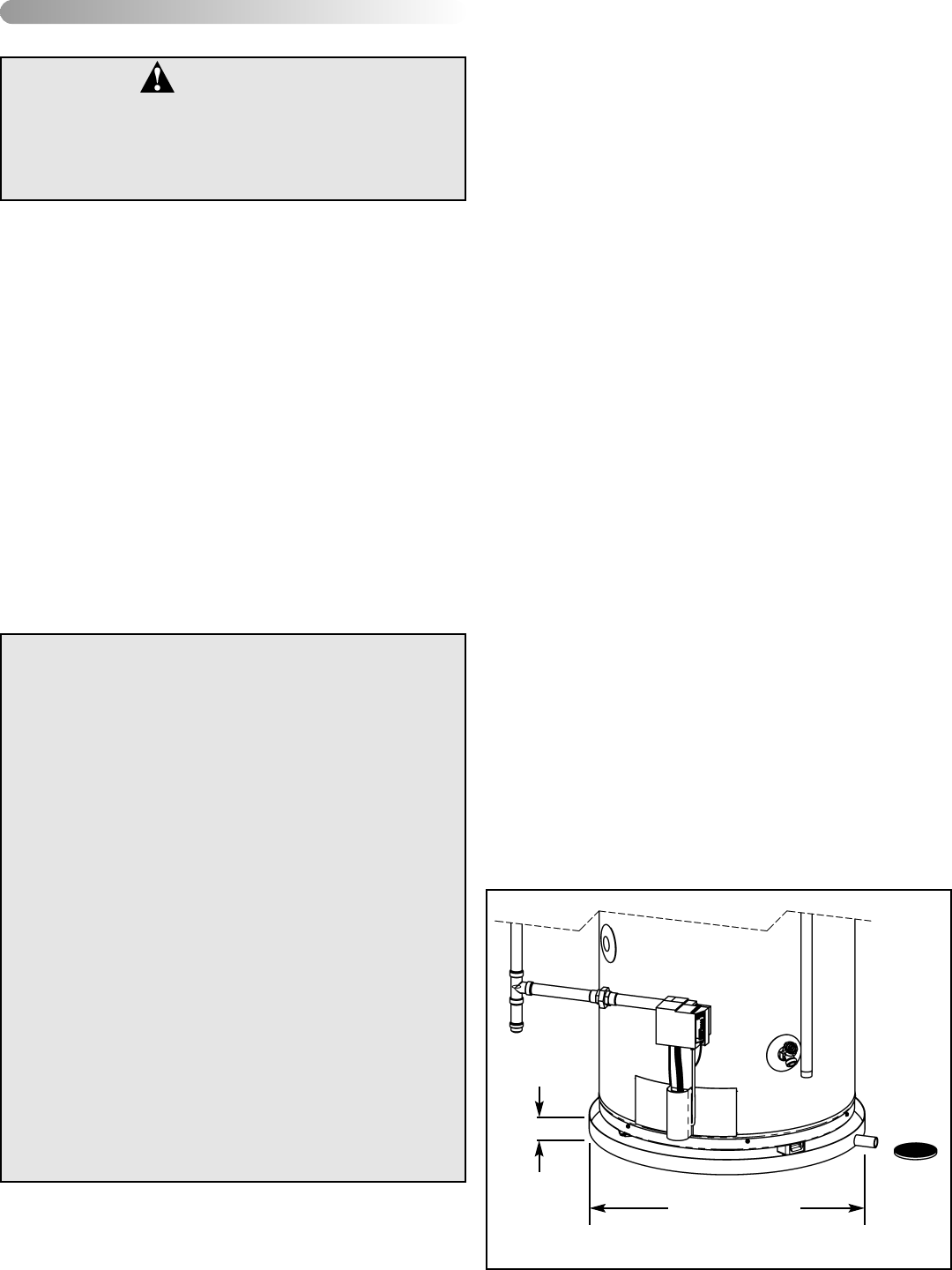
selected, it is recommended that a suitable drain pan be
installed under the water heater. This pan must limit the
water level to a MAXIMUM depth of 45mm (1 3/4 in.) and
have a diameter that is a minimum of 50mm (2 in.) greater
than the diameter of the water heater. Suitable piping shall
connect the drain pan to a properly operating floor drain.
When used with a fuel-fired heater, this drain pan must not
restrict combustion air flow.
45mm
(1 3/4 in.)
MAX
AT LEAST 50mm (2 in.)
GREATER THAN THE
DIAMETER OF THE
WATER HEATER.
PIPE TO
ADEQUATE
DRAIN
Figure 1 Typical Drain Pan Installation
– 6 –