


20
Model VSU Make-Up Air
®®®®®
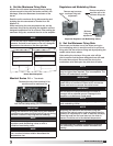
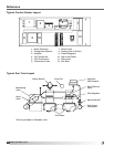
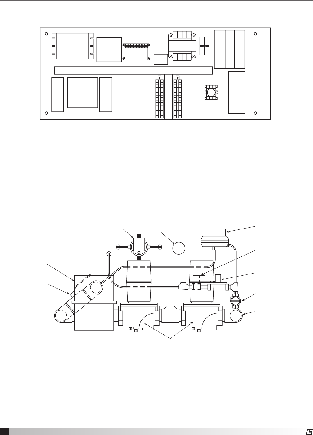
Typical Control Center Layout
Reference
1. Spark Generator
2. Temperature Selector
3. Amplifier
4. 24V Transformer
5. 120V Transformer
6. Transformer Fuses
7. Motor Fuses
8. Heating Inlet Air Switch
9. Flame Safeguard
10. High Limit Switch
11. Disconnect
12. Soft Start
1. Spark Generator
2. Temperature Selector
3. Amplifier
4. 24V Transformer
5. 120V Transformer
6. Transformer Fuses
7. Motor Fuses
8. Heating Inlet Air Switch (optional)
9. Flame Safeguard
10. Freeze Protection (optional) Remove from drawing
10. High Limit Switch
11. Disconnect
12. Starter Overload Soft Start
This drawing is from Part #456857 - Make-Up Air Units with Direct Fired Gas Heater Options
1/26/09 - Additional editing from Scott Laurila for the VSU IOM.
Remove Item #11 - Freeze Protection
Item #8 is a Heating Inlet Air Switch
Item #12 - rename to Soft Start
Rearranged the numbers to read left to right on top & bottom
1
2
4
3
98 10
11
12
7
6
5
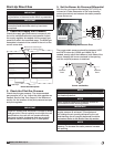
Typical Gas Train Layout
Airflow Switch*
Modulating
Valve
Hand
Valve
Fluid Valve
View Port
High/Low
Gas Pressure
Pilot Solenoid
Valve
Pilot Regulator
Manual Shutoff*
Gas Supply
Connection
This drawing is from Part #456857 - Make-Up Air Units with Direct Fired Gas Heater Options
*Two are provided on Canadian units.