


11
Model VSU Make-Up Air
®®®®®
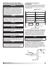
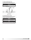
4. Set the Maximum Firing Rate
Monitor the unit’s actual temperature rise by placing
a thermocouple in the unit’s inlet and a second in the
discharge, three duct diameters downstream of the
burner.
Send the unit to maximum fire by disconnecting and
isolating the wire connected to Terminal 4 on the
Maxitrol 14.
While monitoring the units temperature rise, set the
maximum firing rate by adjusting the regulator until the
designed temperature rise is achieved. After setting the
maximum firing rate, reconnect the wire to the amplifier.
NOTE
The minimum setting for the maximum firing rate
may be higher than required. This is acceptable. The
burner will modulate as needed.
NOTE
Do not set the burner maximum firing rate based on gas
pressure. It should be set based on the unit’s designed
temperature rise shown on the direct gas label.
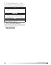
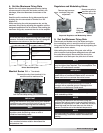
Maxitrol Series 14 — 7 terminals
Remove the wire from terminal #4 to
send the unit to maximum fire
Low fire time delay setting (75% of maximum)
Remove cap to access
maximum firing rate
adjustment
Remove one wire to
send the unit to the
minimum firing rate
Separate Regulator and Modulating Valves
Regulators and Modulating Valves
Minimum
firing rate
adjustment
IMPORTANT
Setting the maximum firing rate during mild weather
conditions may cause the high limit to trip out during
extreme conditions requiring manual resetting.
NOTE
Gas trains are equipped with either separate
regulators and modulating valves or with a
combined modulating valve.
NOTE
Clockwise rotation increases the temperature
rise, counterclockwise rotation decreases the
temperature rise.
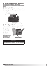
5. Set the Minimum Firing Rate
Disconnect and isolate one of the wires running to
the modulating valve to send the unit to its minimum
firing rate. Set the minimum firing rate by adjusting the
needle valve shown above.
After setting the minimum firing rate, shut off the
pilot to ensure that the flame safeguard can still read
the main flame signal. Reconnect the wire to the
modulation valve and open the pilot shut-off valve.
IMPORTANT
The proper minimum firing rate setting results in a
small ribbon of continuous flame which covers the
flame road and runs across the entire burner.
IMPORTANT
Do not allow the disconnected wire to come in
contact with a potential ground. Damage to the
amplifier or transformer could result.
NOTE
Gas trains are equipped with separate regulators
and modulating valves.
NOTE
Adjusting the maximum and minimum firing rate
requires the inlet air sensor to be set higher than the
outdoor air temperature in order to start the burner(s).
Once high and low fire have been set, the inlet air
sensor should be set to the desired temperature.
NOTE
Counterclockwise rotation increases the minimum
fire rate setting, clockwise rotation decreases the
setting.
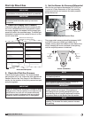
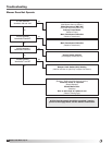
Direct Gas Nameplate
“ W.C.
“ W.C.
F
PSI
“ W.C.
MIN GAS
PRESSURE
PRESSION DE GAZ
MIN BURNER
PRESSURE DROP
PERTE MIN DE PRESSION
DANS LE BRULEUR
TYPE OF GAS
NATURE DU GAZ
MAX BURNER
PRESSURE DROP
PERTE MAX DE PRESSION
DANS LE BRULEUR
MAX GAS
PRESSURE
PRESSION DE GAZ
MAX
DESIGN ∆T
∆T NORMALE
EQUIPPED FOR
CONCU POUR
SCFM
“ W.C.
EXTERNAL STATIC PRESSURE
PRESSION STATIQUE EXTERIEURE
AGAINST
CONTE