


7
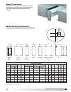
Model MSCF Modular Small Cabinet Fan
®
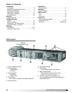
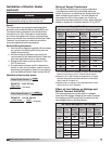
Coil Dimensions
NOTE
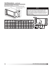
Fluid enters the coil from the bottom connection
(Inlet) and exits from the top (Outlet).
Hot Water • 1 and 2 Row
Unit
Size
Face
Area
A B C D E F
15 1.6 38 12.75 11.0 3.0 0.75 .5
20 2.2 38 12.75 14.0 4.5 0.75 .5
25 2.7 38 12.75 16.0 4.0 0.88 .5
30 3.2 38 12.75 18.5 4.0 0.88 .5
45 4.5 50 12.75 18.5 4.0 0.88 .5
50
5.2 50 12.75 21.0 4.0 1.13 .5
65 6.7 50 12.75 26.0 4.0 1.38 .5
85 8.6 62 12.75 26.0 4.0 1.38 .5
All dimensions are in inches.
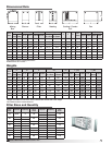
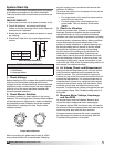
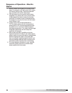
Unit
Size
Face
Area
A B C D E F G
15 1.6 38 15.50 9.38 3.188 0.750 4.0 11.0
20 2.2 38 15.50 9.38 3.188 0.750 4.5 14.0
25 2.7 38 15.50 9.38 3.188 0.875 4.0 16.0
30 3.2 38 15.50 9.38 3.188 0.875 4.0 18.8
45 4.5 50 15.50 9.38 3.188 1.375 4.0 21.0
50 5.2 50 15.50 9.38 3.188 1.375 4.0 26.0
65 6.7 50 15.50 9.38 3.188 1.375 4.0 26.0
85 8.6 62 12.75 9.38 3.188 1.375 4.0 26.0
All dimensions are in inches.
NOTE
With airflow from left to right, the fluid enters the coil
from the bottom connection (Inlet) and exits from the
top (Outlet). The other two coil connections should
be capped off (Cap).
Hot Water • 4 Row
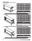
Electric Heat • See our Computer Aided Product Selection (CAPS) Software Program for dimensional data.
Unit
Size
Face
Area
A B C D E F G
15 1.6 38 15.50 7.75 3.31 1.5 5.18 11.0
20 2.2 38 15.50 7.75 3.00 1.5 6.50 14.0
25 2.7 38 15.50 7.75 3.31 2.5 7.69 16.0
30 3.2 38 15.50 7.75 3.00 2.5 9.00 18.5
45 4.5 50 15.50 7.75 3.00 2.5 9.00 18.5
50 5.2 50 15.50 7.75 4.31 2.5 10.18 21.0
65 6.7 50 15.50 7.75 3.00 2.5 12.50 26.0
85 8.6 62 15.50 7.75 3.00 2.5 12.50 26.0
All dimensions are in inches.
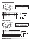
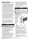
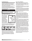
NOTE
Steam enters the coil from the center connection
(Inlet) and exits from the bottom (Outlet).
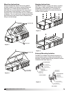
Steam • 1 and 2 Row
B
C
Inlet
Outlet
G
D
F
E
A
Outlet
Inlet
B
G
D
F
E
A
C
Outlet
Inlet
B
6
D
F
3
E
A
C