


10
Model MSCF Modular Small Cabinet Fan
®
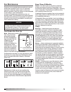
any two supply power connections will reverse the
direction of rotation.
To reverse the rotation, turn the power off and use the
following procedure:
• Forsinglephaseunits,rewirethemotorperthe
instructions on the motor.
• Forthreephaseunits,interchangeanytwo
power leads. This can be done at the motor
starter.
3. Check for Vibration
Check for unusual noise, vibration or overheating of
bearings. Excessive vibration may be experienced
during initial start-up. Left unchecked, excessive
vibration can cause a multitude of problems, including
structural and/or component failure. Many conditions
can be discovered by careful observation. If the
problem is wheel unbalance, in-place balancing can
be done providing there is access to the fan wheel.
Generally, fan vibration and noise is transmitted
to other parts of the building by the ductwork. To
eliminate this undesirable effect, Greenheck has
used a heavy canvas connection between the scroll
and the discharge of the fan. If noise is an issue, we
recommend using heavy canvas connections on the
inlet of the fan. Refer to the Troubleshooting section of
this manual if a problem develops.
4. Air Volume Check and Measurement
Along with the building balance, the unit’s air volume
(cfm) should be measured and compared with its
rated air volume. This unit is flexible for varying air
volume, but the actual air volume should be known for
making final adjustments. The most accurate way to
measure the air volume is by using the pitot traverse
method in the ductwork away from the blower. Other
methods can be used, but should be proven and
accurate. To adjust the air volume, change the fan rpm
or the system losses. See Troubleshooting section in
this guide.
5. Measure Motor Voltage, Amperage
and Fan RPM
All access doors must be installed. Measure and
record the input voltage and motor amperage(s).
To measure the fan RPM, the blower door will need to
be removed. Minimize measurement time because the
motor may over amp with the door removed.
Compare measured amps to the motor nameplate
full load amps and correct if over amping. See the
Troubleshooting section in this guide.
1. Check Voltage
Before starting the unit, compare the supplied voltage
with the unit’s nameplate voltage and the motor
voltage. Units are not provided with thermal overload
protection unless a control center has been ordered
with the unit or the motor has been selected with
thermal overload protection.
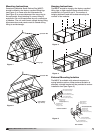
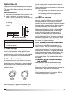
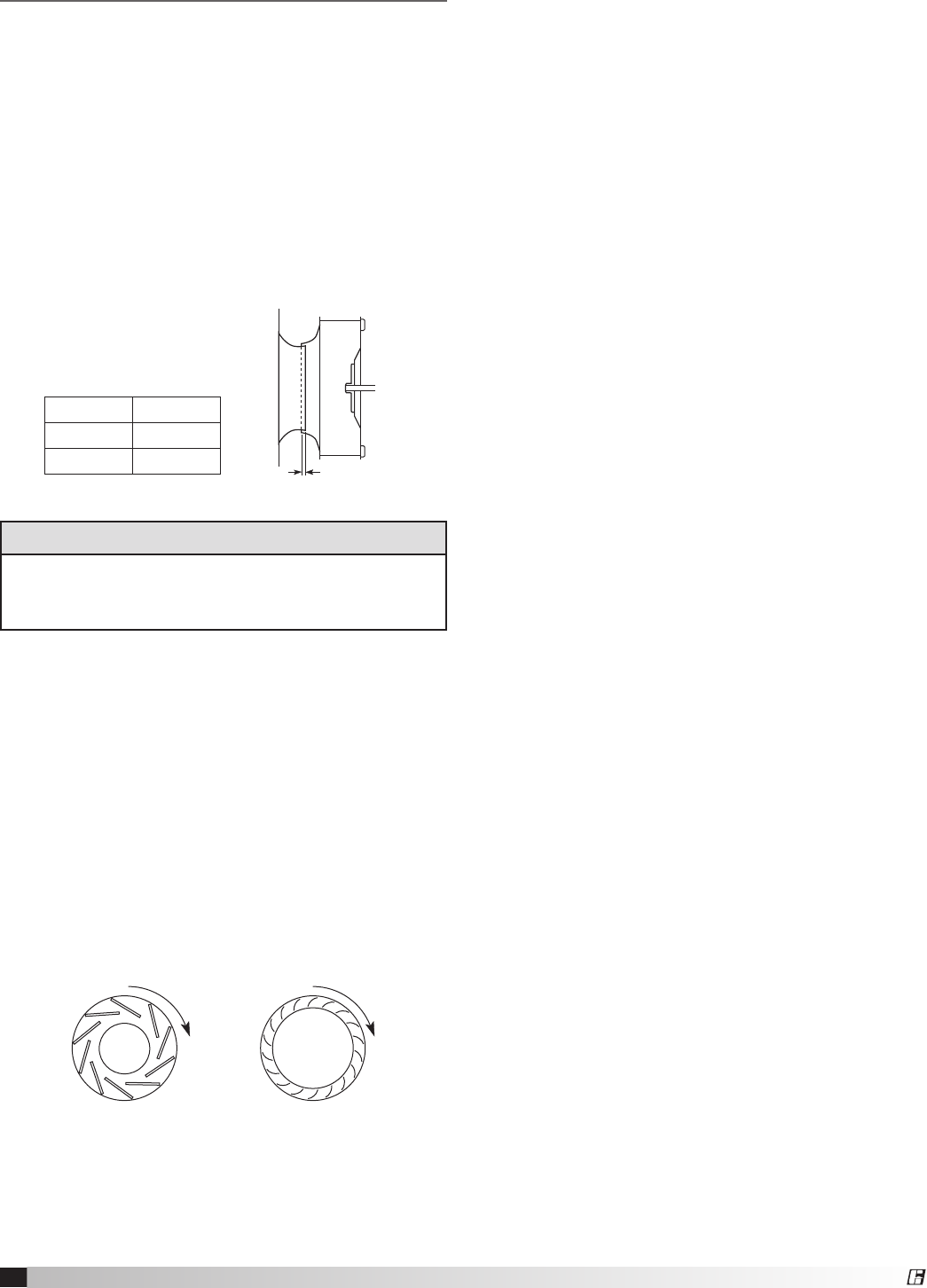
2. Check Blower Rotation
A common problem is wheel rotation in the wrong
direction. For centrifugal fans, incorrect wheel rotation
will provide poor air performance, motor overloading
and possible burnout. Rotation should be checked
while the fan is coasting to a stop. Proper wheel
rotation is shown.
When connecting a 3-phase motor, there is a 50%
chance that the fan will run backwards. Changing
SPECIAL TOOLS REQUIRED
•VoltageMeter
•Tachometer
•AmperageMeter
Backward
Inclined
Airfoil
Forward
Curved
R
o
t
a
t
i
o
n
R
o
t
a
t
i
o
n
R
o
t
a
t
i
o
n
Backward
Inclined
Airfoil
Forward
Curved
R
o
t
a
t
i
o
n
R
o
t
a
t
i
o
n
R
o
t
a
t
i
o
n
Proper Wheel Rotation
C
l
o
c
k
w
i
s
e
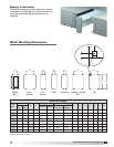
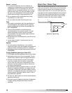
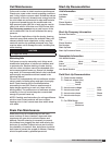
Belt Span
Deflection =
Belt Span
64
G
CORRECT WRONG WRONG WRONG
Unit Size G
25 - 50 1/4 inch
65 - 85 3/8 inch
Wheel Overlap Dimensions
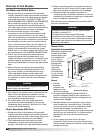
System Start-Up
For proper unit function and safety, follow everything
in this start-up procedure in the order presented.
This is to be done after the electrical connections are
complete.
PRE-START CHECK LIST
1. Disconnect and lock-out all power switches to fan.
2. Check all fasteners, set screws and locking
collars on the fan, bearings, drive, motor base and
accessories for tightness.
3. Rotate the fan wheel by hand and assure no parts
are rubbing.
4. Check the V-belt drive for proper alignment and
tension.