


4
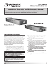
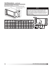
Model MSCF Modular Small Cabinet Fan
®
Hanging Bracket
Part No. 710774
Drawing No. 85537
Hanging Bracket
Part No. 710774
Drawing No. 85537
Bridge Bracket
Part No. 711779
Drawing No. 89814
One required per assembly
Bridge Bracket
Part No. 711779
Drawing No. 89814
One required per assembly
3/4 inch Flat Washer
One required per assembly
3/4 inch Flat Washer
One per assembly as needed
3/8-16x3/4 Spinlock Bolt
Two required per assembly
3/8-16x3/4 Spinlock Bolt
Two required per assembly
3.0 inch
3/8-16 Spinlock Nut
Two required per assembly
3/8-16 Spinlock Nut
Two required per assembly
HANGING ASSEMBLY
BASE ASSEMBLY
Hanging Bracket
Part No. 710774
Drawing No. 85537
Hanging Bracket
Part No. 710774
Drawing No. 85537
Bridge Bracket
Part No. 711779
Drawing No. 89814
One required per assembly
Bridge Bracket
Part No. 711779
Drawing No. 89814
One required per assembly
3/4 inch Flat Washer
One required per assembly
3/4 inch Flat Washer
One per assembly as needed
3/8-16x3/4 Spinlock Bolt
Two required per assembly
3/8-16x3/4 Spinlock Bolt
Two required per assembly
3.0 inch
3/8-16 Spinlock Nut
Two required per assembly
3/8-16 Spinlock Nut
Two required per assembly
HANGING ASSEMBLY
BASE ASSEMBLY
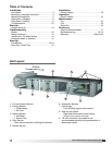
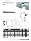
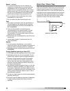
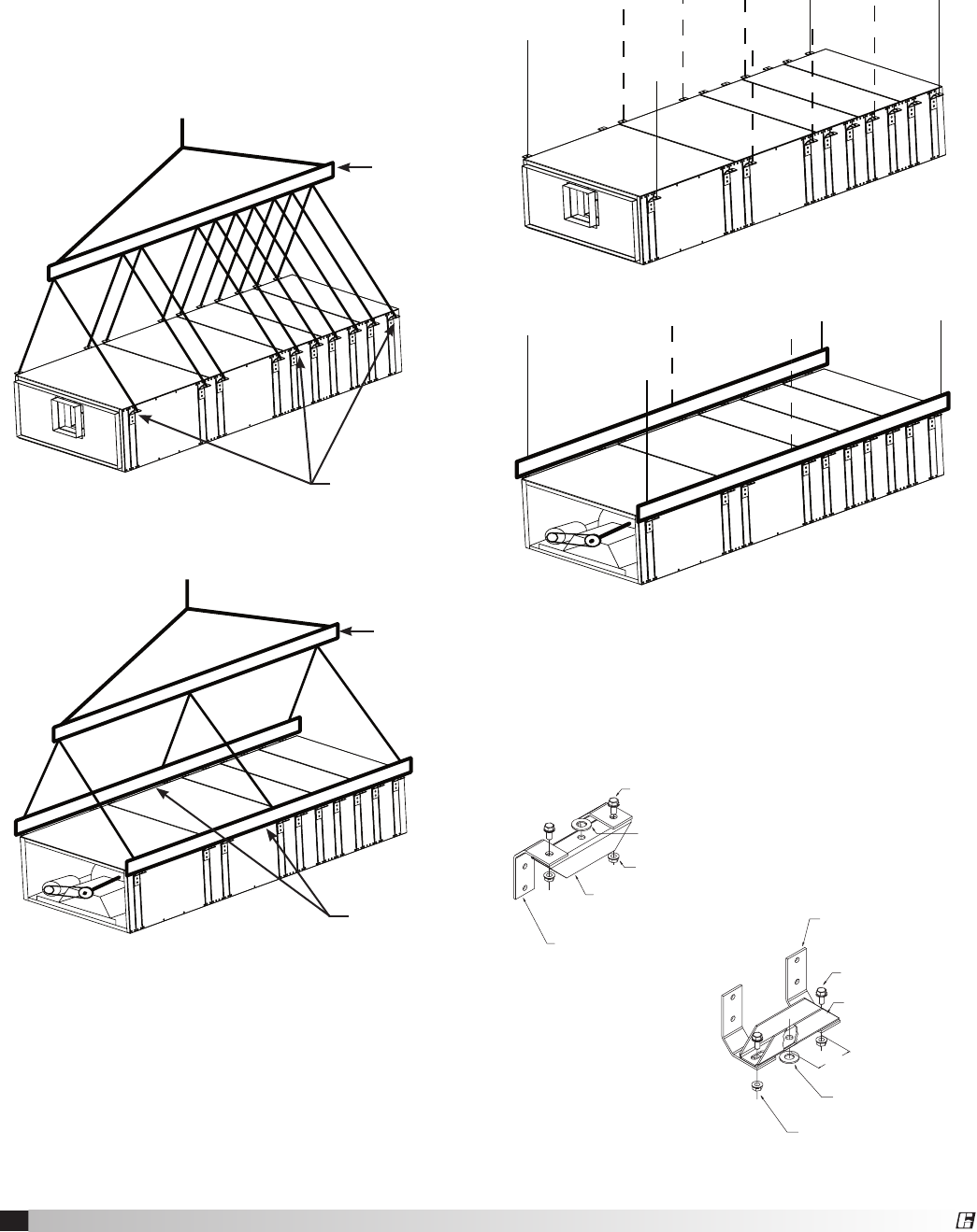
Mounting Instructions
Greenheck’s Modular Small Cabinet Fan (MSCF)
should be lifted by the factory supplied lifting lugs
(see Figure 1) or frame rails and a spreader bar
(see Figure 2) to prevent damage from occurring to
the equipment. Avoid twisting or uneven lifting of
equipment. Do not lift equipment by coil connections
or headers. The unit must remain upright during lifting.
All access doors and panels must be closed during
lifting to avoid damage.
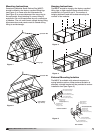
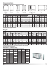
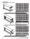
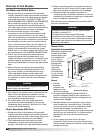
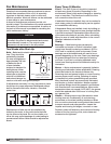
Hanging Instructions
The MSCF should be hung by the factory supplied
lifting lugs or field supplied frame rails as shown
respectively in Figures 3 and 4. The number of
hanging brackets used will be determined by the
number of fan modules.
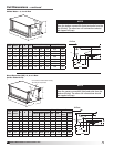
External Mounting Isolation
The MSCF is available with external neoprene or
spring isolation options. When external isolation is
selected, a bridge bracket will be provided to reduce
installation time (see Figure 5).
Figure 4
Figure 5
Figure 3
Figure 1
Lifting lugs
Spreader Bar
Frame Rails
(by others)
Figure 2
Spreader Bar