


6
Model LFC Low-Profile Fan Coil
®
Unit
Size
A B
4 row 6 row 8 row
C D C D C D
30 12.00 7.00 0.625 0.625 0.625 0.875 0.625 0.875
45 12.00 7.00 0.625 0.625 0.625 0.875 0.625 0.875
50 13.50 7.75 0.625 0.625 0.625 0.875 0.625 1.125
65 17.00 9.50 0.875 0.875 0.875 1.125 0.875 1.125
85 17.00 9.50 0.875 0.875 0.875 1.125 0.875 1.125
All dimensions are in inches.
Unit
Size
A
4 row 6 row 8 row
B C B C B C
15 5.75 0.625 0.625 0.625 0.625 0.625 1.375
20 7.0 0.625 0.625 0.625 0.625 0.625 1.375
25 8.0 0.875 1.375 0.875 1.375 0.875 1.375
30 9.5 0.875 1.375 0.875 1.375 0.875 1.375
45 9.5 0.875 1.375 0.875 1.375 0.875 1.375
50 10.75 0.875 1.375 1.125 1.375 0.875 1.625
65 13.00 1.125 1.375 1.125 1.375 1.125 1.625
85 13.00 1.125 1.375 1.125 1.375 1.125 1.625
All dimensions are in inches.
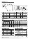
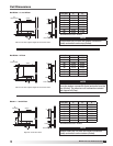
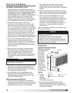
NOTE
With airflow from left to right, the fluid enters the coil
from the bottom connection (Inlet) and exits from the
top (Outlet). The other two coil connections should
be capped off (Cap)
Chilled Water • 4, 6 or 8 Row
Unit Size A
4 row 6 row 8 row
B B B
15 7.63 0.75 0.75 1.375
20 10.13 0.75 0.75 1.375
25 12.63 0.875 0.875 1.375
30 15.13 0.875 0.875 1.375
45 15.13 0.875 0.875 1.375
50 17.63 1.375 1.375 1.625
65 22.63 1.375 1.375 1.625
85 22.63 1.375 1.375 1.625
All dimensions are in inches.
A
3.75
2
1.5
B
Copper Sweat
0.75
1
Drain Connection
3
Outlet
Airflow
LFC-85
LFC-65
LFC-50
1.375
1.375
1.375
LFC-25
LFC-45
LFC-30
LFC-20
LCF-15
Unit Size
A
0.875
0.875
0.875
0.75
0.75
B (4 Row)
22.63
22.63
17.63
12.63
15.13
15.13
7.63
10.13
1.375
1.375
1.375
0.875
0.875
0.875
0.75
0.75
B (6 Row)
1.625
1.625
1.625
B (8 Row)
1.375
1.375
1.375
1.375
1.375
3.75
A
A
B
MSCF-20
MSCF-25
MSCF-30
Unit Size
MSCF-15
7.0
9.5
8.0
5.75
A
C (4 Row)
B (4 Row)
13.00
13.00
10.75
9.5
MSCF-45
MSCF-50
MSCF-65
MSCF-85
0.75
3
Outlet
1
Drain Connection
0.75
3
Outlet
1
Drain Connection
C (6 Row)
B (6 Row)
C (8 Row)
B (8 Row)
0.625
0.625
0.875
0.875
0.875
0.875
1.125
1.125
0.625
1.375
0.625
1.375
1.375
1.375
1.375
1.375
0.625
0.625
0.875
0.875
0.875
1.125
1.125
1.125
0.625
1.375
0.625
1.375
1.375
1.375
1.375
1.375
0.625
0.625
0.875
0.875
0.875
0.875
1.125
1.125
1.375
1.375
1.375
1.625
1.625
1.625
1.375
1.375
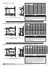
Chilled Water 4,6 or 8 Row
Direct Expansion (DX)-Single Circuit-4,6 or 8 Row
3.75
MSCF-30
Unit Size
12.00
A
D (4 Row)
C (4 Row)
17.00
17.00
13.50
12.00
MSCF-45
MSCF-50
MSCF-65
MSCF-85
D (6 Row)
C (6 Row)
D (8 Row)
C (8 Row)
0.625
0.875
0.875
0.625
0.875
0.875
0.625
0.875
0.875
0.875
1.125
1.125
0.625
1.125
Direct Expansion (DXI)-Dual Circuit with 50/50 Face
Interlaced Construction-4,6 or 8 Row
Airflow
Airflow
B
9.50
7.75
7.00
9.50
7.00
0.625
0.625
0.625
0.625
0.625
0.875
0.625
0.875
0.625
0.875
0.625
0.875
0.875
0.875
1.125
1.125
JOHNSONRI
03/13/2009
1/1
LFC COIL DIMS
B
Copper Sweat
C
Copper Sweat
C
Copper Sweat
D
Copper Sweat
2
1.5
2
1.5
0.25 vent and drain supplied. Right side connection shown.
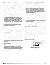
NOTE
With airflow from left to right, the fluid enters the coil
from the center connection (Inlet) and exits from the
bottom (Outlet). The other coil connections should
be capped off (Cap).
Direct Expansion (DX) • Single Circuit • 4, 6 or 8 Row
Distributor hookup is done inside module through 2-inch access hole.
Right side connection shown.
A
3.75
2
1.5
B
Copper Sweat
0.75
1
Drain Connection
3
Outlet
Airflow
LFC-85
LFC-65
LFC-50
1.375
1.375
1.375
LFC-25
LFC-45
LFC-30
LFC-20
LCF-15
Unit Size
A
0.875
0.875
0.875
0.75
0.75
B (4 Row)
22.63
22.63
17.63
12.63
15.13
15.13
7.63
10.13
1.375
1.375
1.375
0.875
0.875
0.875
0.75
0.75
B (6 Row)
1.625
1.625
1.625
B (8 Row)
1.375
1.375
1.375
1.375
1.375
3.75
A
A
B
MSCF-20
MSCF-25
MSCF-30
Unit Size
MSCF-15
7.0
9.5
8.0
5.75
A
C (4 Row)
B (4 Row)
13.00
13.00
10.75
9.5
MSCF-45
MSCF-50
MSCF-65
MSCF-85
0.75
3
Outlet
1
Drain Connection
0.75
3
Outlet
1
Drain Connection
C (6 Row)
B (6 Row)
C (8 Row)
B (8 Row)
0.625
0.625
0.875
0.875
0.875
0.875
1.125
1.125
0.625
1.375
0.625
1.375
1.375
1.375
1.375
1.375
0.625
0.625
0.875
0.875
0.875
1.125
1.125
1.125
0.625
1.375
0.625
1.375
1.375
1.375
1.375
1.375
0.625
0.625
0.875
0.875
0.875
0.875
1.125
1.125
1.375
1.375
1.375
1.625
1.625
1.625
1.375
1.375
Chilled Water 4,6 or 8 Row
Direct Expansion (DX)-Single Circuit-4,6 or 8 Row
3.75
MSCF-30
Unit Size
12.00
A
D (4 Row)
C (4 Row)
17.00
17.00
13.50
12.00
MSCF-45
MSCF-50
MSCF-65
MSCF-85
D (6 Row)
C (6 Row)
D (8 Row)
C (8 Row)
0.625
0.875
0.875
0.625
0.875
0.875
0.625
0.875
0.875
0.875
1.125
1.125
0.625
1.125
Direct Expansion (DXI)-Dual Circuit with 50/50 Face
Interlaced Construction-4,6 or 8 Row
Airflow
Airflow
B
9.50
7.75
7.00
9.50
7.00
0.625
0.625
0.625
0.625
0.625
0.875
0.625
0.875
0.625
0.875
0.625
0.875
0.875
0.875
1.125
1.125
JOHNSONRI
03/13/2009
1/1
LFC COIL DIMS
B
Copper Sweat
C
Copper Sweat
C
Copper Sweat
D
Copper Sweat
2
1.5
2
1.5
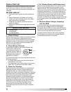
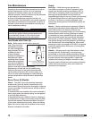
NOTE
The first suction header on the entering air side of
the coil is circuited to the top distributor. With airflow
from left to right, the fluid enters the coil from the
center connection (Inlet) and exits from the bottom
(Outlet). The other coil connections should be
capped off (Cap).
A
3.75
2
1.5
B
Copper Sweat
0.75
1
Drain Connection
3
Outlet
Airflow
LFC-85
LFC-65
LFC-50
1.375
1.375
1.375
LFC-25
LFC-45
LFC-30
LFC-20
LCF-15
Unit Size
A
0.875
0.875
0.875
0.75
0.75
B (4 Row)
22.63
22.63
17.63
12.63
15.13
15.13
7.63
10.13
1.375
1.375
1.375
0.875
0.875
0.875
0.75
0.75
B (6 Row)
1.625
1.625
1.625
B (8 Row)
1.375
1.375
1.375
1.375
1.375
3.75
A
A
B
MSCF-20
MSCF-25
MSCF-30
Unit Size
MSCF-15
7.0
9.5
8.0
5.75
A
C (4 Row)
B (4 Row)
13.00
13.00
10.75
9.5
MSCF-45
MSCF-50
MSCF-65
MSCF-85
0.75
3
Outlet
1
Drain Connection
0.75
3
Outlet
1
Drain Connection
C (6 Row)
B (6 Row)
C (8 Row)
B (8 Row)
0.625
0.625
0.875
0.875
0.875
0.875
1.125
1.125
0.625
1.375
0.625
1.375
1.375
1.375
1.375
1.375
0.625
0.625
0.875
0.875
0.875
1.125
1.125
1.125
0.625
1.375
0.625
1.375
1.375
1.375
1.375
1.375
0.625
0.625
0.875
0.875
0.875
0.875
1.125
1.125
1.375
1.375
1.375
1.625
1.625
1.625
1.375
1.375
Chilled Water 4,6 or 8 Row
Direct Expansion (DX)-Single Circuit-4,6 or 8 Row
3.75
MSCF-30
Unit Size
12.00
A
D (4 Row)
C (4 Row)
17.00
17.00
13.50
12.00
MSCF-45
MSCF-50
MSCF-65
MSCF-85
D (6 Row)
C (6 Row)
D (8 Row)
C (8 Row)
0.625
0.875
0.875
0.625
0.875
0.875
0.625
0.875
0.875
0.875
1.125
1.125
0.625
1.125
Direct Expansion (DXI)-Dual Circuit with 50/50 Face
Interlaced Construction-4,6 or 8 Row
Airflow
Airflow
B
9.50
7.75
7.00
9.50
7.00
0.625
0.625
0.625
0.625
0.625
0.875
0.625
0.875
0.625
0.875
0.625
0.875
0.875
0.875
1.125
1.125
JOHNSONRI
03/13/2009
1/1
LFC COIL DIMS
B
Copper Sweat
C
Copper Sweat
C
Copper Sweat
D
Copper Sweat
2
1.5
2
1.5
Direct Expansion (DXI) • Dual Circuit with 50/50 Face Interlaced Construction • 4, 6 or 8 Row
Distributor hookup is done inside module through 2-inch access hole.
Right side connection shown.