


10
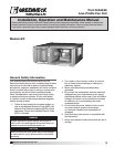
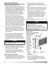
Model LFC Low-Profile Fan Coil
®
Steam Coils, General - continued
3. Standard steam coils are pitched in the casings
when installed for horizontal airflow. The casing
must be level after the unit is installed for proper
condensate drainage. If condensate is not
removed, the coil will suffer from water hammering
and will have a shortened life. On vertical airflow
applications, the coils must be pitched when
installed.
4. Do not reduce pipe size at the coil return
connection. Carry return connection size through
the dirt pocket, making the reduction at the branch
leading to the trap.
5. It is recommended that vacuum breakers be
installed on all applications to prevent retaining
condensate in the coil. Generally, the vacuum
breaker is to be connected between the coil inlet
and the return main. The vacuum breaker should
be open to the atmosphere and the trap design
should allow venting of large quantities of air.
6. Do not attempt to lift condensate when using
modulating or on-off control.
7. Do not reduce the pipe size leaving the coil.
Traps
1. Size traps in accordance with the manufacturer’s
recommendations. Be certain that the required
pressure differential will always be available. DO
NOT UNDERSIZE.
2. Float and thermostatic or bucket traps are
recommended for low pressure steam. On high
pressure systems, bucket traps are normally
recommended. The thermostatic traps should be
used only for air venting.
3. Bucket traps are recommended for use with on-off
control only.
4. Locate traps at least 12 inches below the coil
return connection.
Controls
1. On high pressure installations, a two-position
steam valve with a face and bypass arrangement is
preferred where modulating control is required.
2. Modulating valves must be sized properly. DO NOT
UNDERSIZE.
2P = minimum
2P = minimum
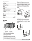
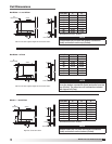
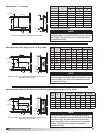
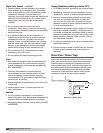
Drain Pan / Drain Trap
Drain Pan / Drain Trap
Drain lines and traps should be run full size from the
drain pan connection. Drain pans should have drain
lines and traps to permit the condensate from the
coils to drain freely. On all units with drain pans, the
trap depth and the distance between the trap outlet
and the drain pan outlet should be twice the static
pressure (P) in the drain pan section under normal
operation to assure the trap remains sealed.
Freezing Conditions (entering air below 35°F)
1. 5 PSI steam must be supplied to the coil at all times.
2. Modulating valves are not recommended. Control
should be by means of face and bypass dampers.
3. Provision should always be made to thoroughly
mix fresh air and return air before it enters the
coil on return air units. Also, temperature control
elements must be properly located to obtain true
air mixture temperatures.
4. As additional protection against freeze-up, the trap
should be installed sufficiently —far below the coil
to provide an adequate hydrostatic head to ensure
removal of condensate during an interruption in the
steam pressure. Estimate 3 feet for each 1 PSI of
trap differential required.
5. On start-up, admit steam to coil ten minutes before
admitting outdoor air.
6. Provision must be made to close fresh air dampers
if steam supply pressure falls below minimum
specified.