


3
Model LFC Low-Profile Fan Coil
®
Table of Contents
Installation
Unit Layout . . . . . . . . . . . . . . . . . . . . . . . . . . . . . . .3
Lifting / Hanging Instructions ................ 3
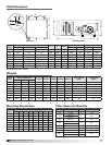
Dimensions / Weights ...................... 4
Filter Sizes / Quantity . . . . . . . . . . . . . . . . . . . . . . 4
Coil Dimensions . . . . . . . . . . . . . . . . . . . . . . . . .5-6
Start-Up
System Start-Up . . . . . . . . . . . . . . . . . . . . . . . . . . 7
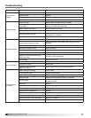
Troubleshooting
Blower . . . . . . . . . . . . . . . . . . . . . . . . . . . . . . . . . . 8
Motor Overamps .......................... 8
Insufficient / Too Much Airflow ............... 8
Excessive Noise or Vibration . . . . . . . . . . . . . . . . 8
Start-Up
Coil Module ............................9-10
Drain Pan / Drain Trap . . . . . . . . . . . . . . . . . . . . 10
Maintenance
Fan .................................... 11
Coil .................................... 12
Drain Pan ............................... 12
Reference
Start-Up Documentation ................... 12
Maintenance Log . . . . . . . . . . . . . . . . . . . . . .13-15
Warranty . . . . . . . . . . . . . . . . . . . . . . . . .Backcover
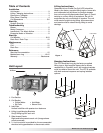
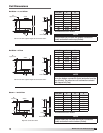
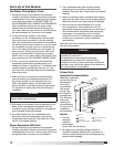
Unit Layout
Lifting Instructions
Greenheck’s Low-Profile Fan Coil (LFC) should be
lifted by the factory supplied lifting lugs or frame rails
and a spreader bar (by others) to prevent damage
from occurring to the equipment (see Figure 1). Avoid
twisting or uneven lifting of equipment. Do not lift
equipment by coil connections or headers. The unit
must remain upright during lifting. All access doors
and panels must be closed during lifting to avoid
damage.
1. Fan Section
2. Coil Section
• ChilledWater • HotWater
• DXCoils • SteamCoils
3. Inlet Filter
Vertical inlet filter with quarter-turn fasteners
4. Lifting Lugs/Hanging Brackets
Six (6) lifting lugs for each unit
5. Side Access Panels
Right and left access to each unit. (Image shows
panels removed).
6. 1
1
⁄4 inch knockout is provided for the recommended
electrical wiring penetration or disconnect switch.
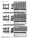
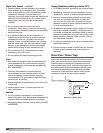
Hanging Instructions
The LFC should be hung by the factory supplied
lifting lugs or field supplied frame rails as shown
respectively in Figures 2 and 3. All hanging brackets
must be used to mount the unit. The LFC is available
with both external neoprene and spring isolation
options.
Figure 2
Figure 3
Frame Rails
Spreader Bar
Lifting Lugs
Figure 1
Airflow
2
4
5
5
1
6
3