


308655J 11
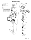
Air Motor and Throat Service
L
05612
25
16
23
15
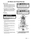
Turn
lock-
wires
up.
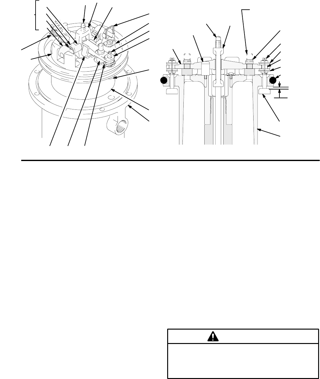
Fig. 4
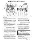
Cut off tops
of poppets as
indicated by
dotted lines.
0.125”
(3.18 mm)
Cutaway View
M
13
31
22*
21*
32*
21*
32*
27
28
32*
21*
17*
31
14
17*
21*
32*
26*
27
26*14
19*
04422
12
13
15
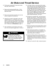
Reassembly
1. Place the piston rod (29) flats in the vise with the
air motor up.
2. Pull the exhaust valve poppets (26*) into the valve
actuator (12), and clip off the top parts of the
poppets (shown with dotted lines in the Cutaway
View in Fig. 4).
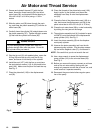
3. Install the lower valve grommets (17*) in the
actuator (12), place the inlet valve poppets (32*) in
the piston, and thread the bottom valve nuts (21*)
onto the inlet valve poppets until there are a few
threads left before the threads run out.
NOTE: If you thread the valve nuts too far down
onto the poppets, they will run off of the
threaded part of the poppets.
4. Grease heavily and place the trip rod (31) in the
piston, place the actuator (12) in the yoke (13),
and place the well-greased actuator/yoke assem-
bly in the piston, with the trip rod going through the
center holes of the actuator and yoke and the inlet
valve poppets (32*) going through the lower valve
grommets (17*).
5. Thread the top valve nuts (21*) onto the inlet valve
poppets (32*) until one thread of the inlet valve
poppets is exposed above the valve nuts.
6. Install the toggle pins (15) in the yoke (13), place
the toggle arm (23) ends of the toggle assembly
(M) onto the toggle pins, and snap the pivot pin
(16) ends of the toggle assembly into the lugs (L).
7. Measuring with the gauge (Part No.171818),
create 0.125-in. (3.18 mm) of clearance between
the inlet valve poppets (32*) and the piston seat
when the inlet valve is open. See the Cutaway
View Fig. 4.
NOTE: Adjust the distance between the inlet valve
poppets and the piston seat by turning the
top valve nuts (21*).
8. Tighten the bottom valve nuts (21*) securely by
hand.
9. Align the holes in the valve nuts (21*) and the slots
on the tops of the inlet valve poppets (32*), and
drop the lock wires (22*) through the holes in the
valve nuts and into the slots in the inlet valve
poppets. Pull the lock wires down tightly, and
bend the ends with pliers so that they cannot be
pulled back out of the holes.
Never re-use the old lock wires. They will get
brittle and break easily from too much bending.
When you install new lock wires, do not bend them
too severely, or they may break. See Fig. 4.
CAUTION
10. Grease and install the new o-rings (19* and 20*)
on the piston assembly (27) and in the groove in
the air motor base (28).
11. Clamp the air motor base (28) in a vise horizontally
by closing the vise jaws on the flange.