


Installation
6 3A0538F
Installation
Grounding
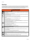
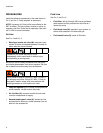
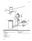
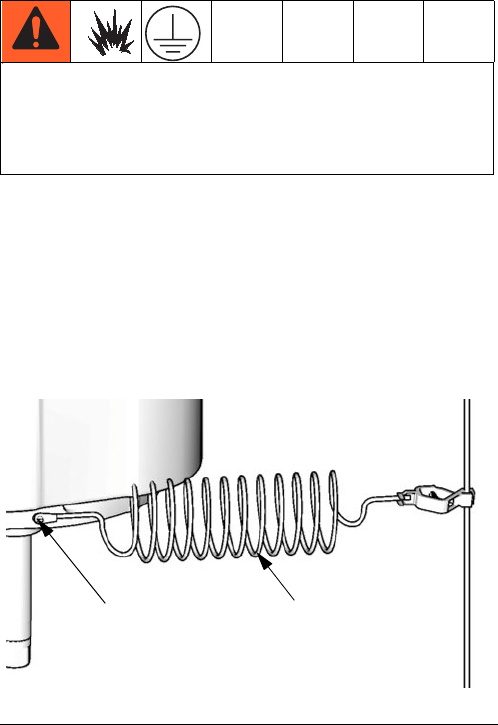
Pump: use a ground wire and clamp. See F
IG
. 1.
Remove the green ground screw (Z) from the bottom of
the air motor. Insert the screw through the loop on the
end of the ground wire (Y) and reattach the screw to the
air motor. Connect the ground clamp to a true earth
ground. Order Part No. 244524, Ground Wire and
Clamp.
Air and fluid hoses: use only electrically conductive
hoses
with a maximum of 500 ft. (150 m) combined
hose length to ensure grounding continuity. Check the
electrical resistance of hoses. If total resistance to
ground exceeds 25 megohms, replace hose immedi-
ately.
Air compressor: follow manufacturer’s recommenda-
tions.
Surge tank: use a ground wire and clamp.
Dispense valve: ground through a connection to a
properly grounded fluid hose and pump.
Fluid supply container: follow local code.
Object being sprayed: follow local code.
Solvent pails used when flushing: follow local code.
Use only conductive metal pails, placed on a grounded
surface. Do not place the pail on a nonconductive sur-
face, such as paper or cardboard, which interrupts
grounding continuity.
To maintain grounding continuity when flushing or
relieving pressure: hold metal part of the spray gun
firmly to the side of a grounded metal pail, then trigger
the gun.
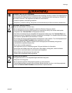
The equipment must be grounded. Grounding
reduces the risk of static and electric shock by
providing an escape wire for the electrical current
due to static build up or in the event of a short circuit.
F
IG
. 1. Ground Wire
TI8250a
Z Y