Repair
Diaphragm and
Center Section Repair
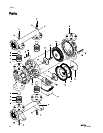
NOTE: Diaphragm kits are available in a range of
materials and styles. See pages 28 – 29. A Center
Rebuild Kit also is available. See page 23. Parts
included in the Center Rebuild Kit are marked with an
*. For best results, use all kit parts.
Disassemble the Diaphragm and Center
Section
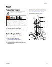
1. Follow the Pressure Relief Procedure, page 11.
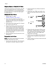
2. Remove the manifolds and disassemble
the ball check valves as explained in
Check Valve Repair, page 14.
NOTE: You
may wish to remove the inner fluid
cover bol
ts (5) as you remove each manifold, for
convenie
nce.
3. Overmol
ded Diaphragms (PO models)
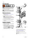
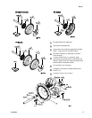
a. Orient the pump so one of the fluid covers
(2) faces up. Use a 17 mm socket wrench to
remove the fluid cover bolts (5, 6), then pull
the fluid cover up off the pump.
b. The exposed diaphragm (12) will screw off by
hand. The shaft will either release and come
off with this diaphragm, or remain attached to
the other diaphragm. If the diaphragm shaft
bolt (14) remains attached to the shaft (108),
remove it. Remove the air side diaphragm
plate (11) and washer (17).
c. Turn the pump over and remove the other
fluid cover. Remove the diaphragm (and the
shaft, if necessary).
d. If the shaft is still attached to either
diaphragm, grasp the diaphragm firmly and
useawrenchontheflatsoftheshaftto
remove. Also remove the air side diaphragm
plate (11) and washer (17). Continue with
Step 5.
4. All Other Diap
hragms
a. Orient the pump so one of the fluid covers
facesup. Usea17mmsocketwrenchto
remove the fluid cover screws (5, 6), then pull
thefluidcover(2)upoffthepump.Turnthe
pump over and remove the other fluid cover.
b. Hold the hex of one fluid side diaphragm
plate (15) with a 1–1/2 socket or box end
wrench. Use another wrench (same size)
on the hex of the other plate to remove.
Then remove all parts of each diaphragm
assembly.
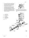
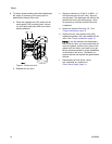
5. Inspect the diaphragm shaft (108) for wear or
scratches. If it is damaged, inspect the bearings
(107) in place. If they are damaged, use a
bearing puller to remove them.
NOTE: Do not remove undamaged bearings.
6. Useano-ringpicktoremovetheu-cuppackings
(106) from the center housing. Bearings (107)
canremaininplace.
7. If necessary, use a socket wrench to remove the
pilot valves (111).
8. Remove the pilot valve cartridges only if
necessary due to a known or suspected problem.
After removing pilot valves, use a hex to remove
the cartridges (109), then remove cartridge
o-rings (110). If stripped, use two screwdrivers to
screw out the cartridge.
NOTE:
Do not remove undamaged pilot valve
cartr
idges.
3A2889A 15


