Repair
Check Valve Re
pair
NOTE: Kits are available for new check valve balls
and seats in a range of materials. See page 27
to order kits in the material(s) desired. O-ring and
fastener kits also are available.
NOTE: To ens
ure proper seating of the check balls,
always repl
ace the seats when replacing the balls.
Also, repla
ce the o-rings every time the manifold is
removed.
Disassemb
le the Check Valve
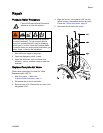
1. Follow the
Pressure Relief Procedure, page 11.
Disconne
ct all hoses.
2. Remove th
e pump from its mounting.
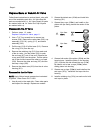
3. NOTE: Use
hand tools until thread-locking
adhesive
patch releases. Use a 17 mm (11/16 in)
socket w
rench to remove the manifold fasteners
(5), the
n remove the manifold (3).
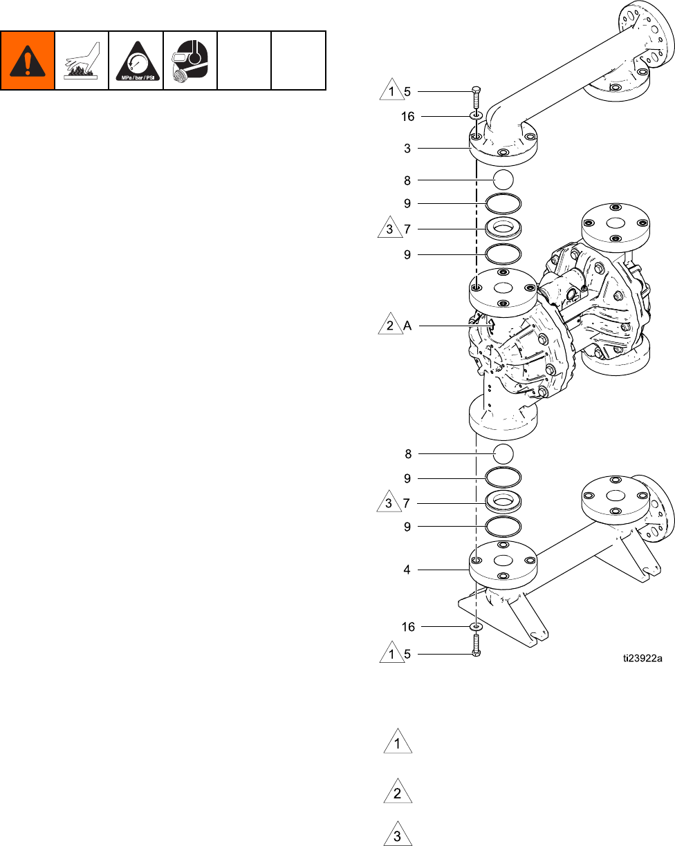
4. Remove t
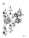
he o-rings (9), seats (7), and balls (8).
5. Turn th
epumpoverandremovetheinlet
manifo
ld (4).
6. Remove
the o-rings (9), seats (7), and balls (8).
Reasse
mble the Check Valve
1. Clean
all parts and inspect for wear or damage.
Repla
ce parts as needed.
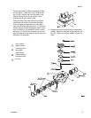
2. Reass
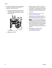
emble in the reverse order, following all
notes
in the illustration. Put the inlet manifold on
first
. Be sure the ball checks (7-9) and manifolds
(3, 4
) are assembled exactly as shown. The ball
must
seat on the chamfered side of the seat.
The a
rrows (A) on the fluid covers (2) must point
towa
rd the outlet manifold (3).
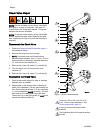
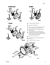
Figure 1 Check valve assembly
Torqueto190to200in-lb(21to25
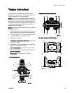
N·m). Follow torque sequence. See
Torque Instructions, page 19.
Arrow (A) must point toward outlet
manifold
The chamfered side of the seat must face
the ball.
1
4
3A2889A


