Installation
Fluid Connect
ions
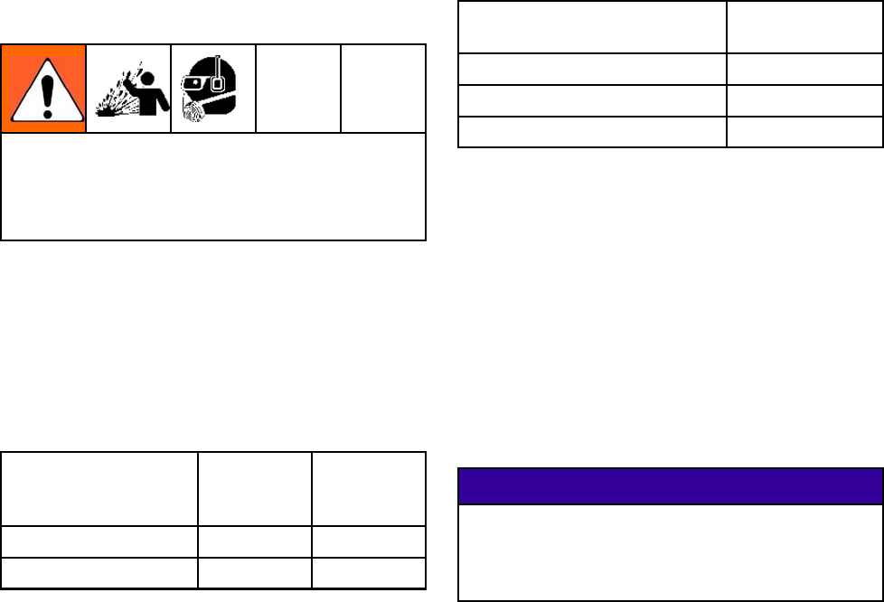
Undue stress on the pump inlet or outlet
connections can cause serious injury or equipment
failure. The fluid inlet and outlet lines must be
independently supported. The pipe supports
should be located as close to the pump as possible.
NOTE: The hose connections require the use of a
hose clamp. Part No. 24L497 Clamping Tool is
available from Graco.
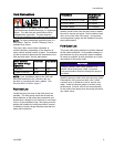
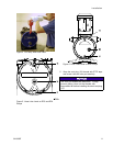
Thepumpro
ller moves either clockwise or
counter-c
lockwise, depending on the direction of
motor rota
tion and the number of gears. The direction
of roller m
ovement determines the orientation of the
fluid inle
t and outlet. See the table below.
Roller Di
rection
(as viewe
d through
sightgla
ss)
Fluid Inl
et
Fluid Outlet
Clockwise Left
Right
Counter-clockwise
Right
Left
NOTE: If your installation requires the fluid inlet
and outlet positions to be reversed, this can
be done by reversing the motor rotation. See
Reverse Motor Direction, page 17.
Fluid Inlet Line
Locate the pump as close to the fluid source as
possible. The inlet piping should be at least the
same diameter as the pump inlet connection and
should have a straight run of pipe that is a minimum
of 8 to 10 pipe diameters long. Inlet piping must be
airtight and suitable for both pressure and vacuum.
If possible, provide a larger diameter pipe than the
pump inlet connection.
Pump Model Fluid Inlet and
Outlet Size
EP2006 and EP2013 Pumps
1/2 npt(m)
EP3019 Pumps
3/4 npt(m)
EP4029 Pumps
1–1/4 npt(m)
Install a sh
utoff valve near the pump inlet to isolate
the unit for
service and repair. Never install a check
valveonthe
inlet side of the pump. A compound
vacuum/pre
ssure gauge can be installed to monitor
pump perfor
mance.
Fluid Outl
et Line
Thepumpo
utlet piping should be a similar diameter
as the out
let connection. Avoid sudden changes in
pipe diam
eter by using concentric taper increasers.
As much as
possible, provide a straight run of pipe
downstr
eam of the pump outlet.
NOTICE
Install a pressure relief valve upstream of a
shutoff valve at the pump outlet, to prevent
over-pressurization that can damage the pump or
the hose.
Install the pressure relief valve near the pump outlet.
Downstream of the pressure relief valve, install
a shutoff valve to isolate the unit for service and
repair. Install a pressure gauge to monitor pump
performance. A check valve is not recommended
on the outlet of the pump since the pump acts as its
own check valve.
3A1938E 9


