


2 308791
Table of Contents
Set-Up 2. . . . . . . . . . . . . . . . . . . . . . . . . . . . . . . . . . . . . . .
Operation 4. . . . . . . . . . . . . . . . . . . . . . . . . . . . . . . . . . . . .
Maintenance 6. . . . . . . . . . . . . . . . . . . . . . . . . . . . . . . . . .
Parts
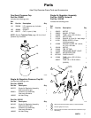
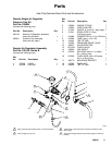
One Quart Pressure Cup 239801 7. . . . . . . . . . . . .
Single Air Reg 7
Pressure Cup Kit 239802, 245181 7. . . . . . . . . . . .
Single Air Reg. Assembly 235375, 245192 7. . . . .
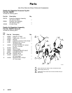
Double Air Reg. Pressure Cup Kit 239803 8. . . . . .
Double Air Reg. Assembly 235376 8. . . . . . . . . . . .
Remote Single Air Reg. 9. . . . . . . . . . . . . . . . . . . . .
Pressure Cup Kit 239804 9. . . . . . . . . . . . . . . . . . . .
Remote Single Air Reg. Assembly 236142 9. . . . .
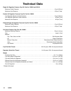
Technical Data 10. . . . . . . . . . . . . . . . . . . . . . . . . . . . . . .
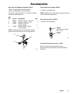
Accessories 11. . . . . . . . . . . . . . . . . . . . . . . . . . . . . . . . .
Warranty 12. . . . . . . . . . . . . . . . . . . . . . . . . . . . . . . . . . . .
Graco Information 12. . . . . . . . . . . . . . . . . . . . . . . . . . . .
Setup
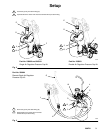
NOTE: Tighten all fittings securely.
Install the Elbow Fitting and Tubing
Push the tubing (3), with the check valve (13), firmly
into the cup’s elbow fitting (D). See Fig. 2 or 3. The
tapered side of the check valve must face towards the
cup’s elbow fitting.
NOTE: To disconnect the tubing, push down on the
fitting’s outer ring and pull on the tubing.
Part No. 239802, 239803, and 245181:
Install the Gun on the Cup
1. Tighten the cup swivel fitting (E) onto the gun fluid
inlet. See Fig. 2.
2. Tighten the air fitting (F) onto the gun air inlet.
Part No. 239804: Assemble the Remote
Single Air Regulator Pressure Cup Kit
1. Tighten the cup swivel fitting (E) onto the fluid
outlet fitting (4) of the air regulator assembly. See
Fig. 3.
2. Tighten the air supply line (G) onto the air inlet
fitting (19).
3. Tighten the air line (H) onto the gun air inlet.
4. Tighten the fluid line (J) onto the gun fluid inlet.
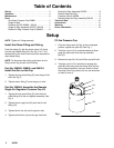
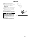
Fill the Pressure Cup
1. Push the clamp lever (A) fully to the unclamped
position, against the yoke (B). See Fig. 1.
2. Twist the cup lid (101) counterclockwise to disen-
gage the yoke hook from the cup extended
pins (C).
3. Remove the cup lid (101) and fill the cup with fluid.
4. Twist the cup lid (101) clockwise to engage the
yoke (B) hook, then push the clamp lever (A) fully
to the clamped position. Use your thumb to force
the clamp lever into position; do not use wrenches
or tools to move it.
Fig. 1
A
101
B
103
C
01961
A