


Setup
8 3A2257C
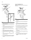
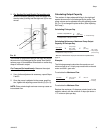
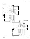
Connecting Lube Lines to Pump: Suction,
Gravity and Pressure Fed Pump Models
Only
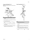
NOTE: The lube line refers to the outlet line supplying
lubricant to the lubrication points.
1. Apply thread sealant (user supplied) to lube line fit-
ting.
2. Connect lube line to pump outlet (6), (F
IG. 8)(also
see pages 15 and 16).
3. Torque lube line fitting to 50 +
5 in. lbs (5.65 + 0.6
N.m).
If inst
4. If installed, close the drain valve, located down-
stream from the pump.
5. Hand prime the pump until clean, air-free oil is flow-
ing through the lube line.
6. Connect the lube line to the lube point.
7. After startup, adjust individual pumps to meet
required flow rates. See Adjusting the Pump, page
8.
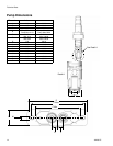
Alarm Models Only: Installing Pressure
Sensor (see Alarm Pump, page 17)
1. Apply thread sealant (user supplied) to pressure
sensor.
2. Install pressure sensor into sensor output (3) (F
IG.
7).
NOTE: Sensor output will open at 100 - 200 psi
(6.89 bar, 0.68 MPa).
3. After startup, ensure sensor is activating correctly.
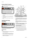
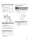
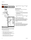
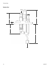
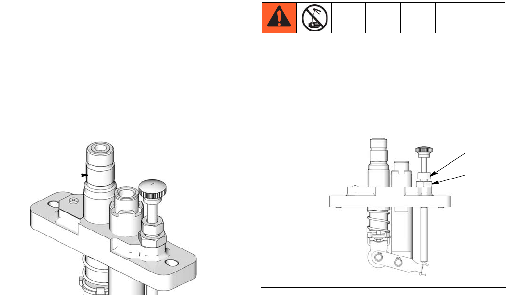
Adjusting the Pump
Pump volume is controlled by an external adjusting
screw (8) (F
IG. 9). Turning the adjusting screw changes
the length of the piston stroke which changes the pump
discharge volume.
1. Loosen the adjusting screw locknut (9) (F
IG. 9).
2. Turn the adjusting screw (8) (F
IG. 9):
• Counterclockwise - increases discharge volume
(drops per stroke)
• Clockwise - decreases discharge volume (drops
per stroke)
FIG. 8
6
I
FIG. 9
9
8