


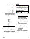
Warnings
4 3A2257C
Pressure Relief Procedure
1. Stop lube pump.
2. If installed, close oil supply valve located upstream
from pump.
3. If installed, open drain valve located downstream
from the pump.
4. Slowly crack open fluid line fittings to relieve pres-
sure.
Installing the Pump
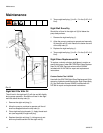
Grounding
Ensure the reservoir is properly grounded as the pump
is grounded through the mounting screws.
Mounting Pump
NOTE:
• Ensure box and lube system are sized appropriately
for the selected pressure.
• Ensure an appropriate pressure relief device, suit-
able for your application, is installed in the system.
• Inspect your box lubricator and replace any dam-
naged or worn components.
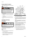
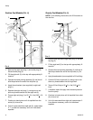
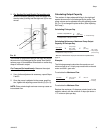
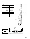
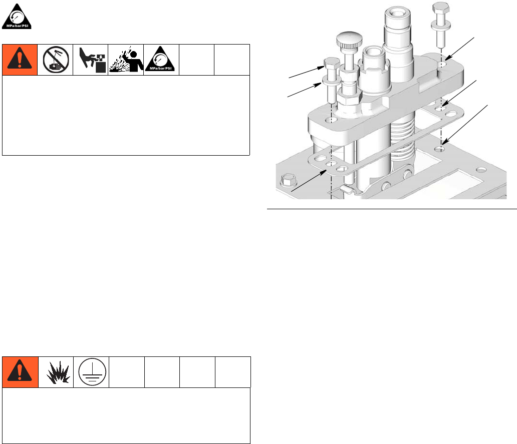
1. Ensure the pump mounting surface on the reservoir
cover is clean. Clean as needed.
2. Align gasket (a) with opening on the top of the reser-
voir cover making sure holes (b) on either end of the
gasket match mounting holes (c) in reservoir cover
(F
IG. 1).
NOTE: Alarm Pumps Only - For optimum perfor-
mance, mount alarm pump in location furthest from
drive motor.
• For Gravity and Pressure Fed pumps, skip Step
3 and continue installation with Step 4.
• For Alarm pumps skip Step 3a and continue
installation with Step 3b.
• Pressure Fed pumps follow Step 3a and 3b.
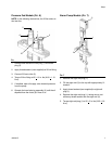
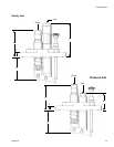
3. For Suction Fed Pumps install pump inlet strainer:
a. Check length of suction tube. If it is too long to
fit in the reservoir, use a pliers to break off the
lower section of the tube (a) (F
IG. 2).
Follow the Pressure Relief Procedure whenever
you see this symbol.
I
This equipment stays pressurized until pressure is
manually relieved. To help prevent serious injury from
pressurized fluid, such as skin injection, splashing
fluid and moving parts, follow the Pressure Relief
Procedure when you stop pumping and before
cleaning, checking or servicing the equipment.
The equipment must be grounded to reduce the risk
of static sparking. Static sparking can cause fumes to
ignite or explode. Grounding provides an escape wire
for the electric current.
FIG. 1
d
c
a
b
e
f